
AutoCAD for Architects
Welcome to our AutoCAD course for Architects.
In it we explain how to use AutoCAD to design and layout a building.
Starting with the basics of setting up a file we walk you through the process step-by-step.
By the end you will be able to complete a design starting with only an aerial photograph of your site.
Along the way we will share 24 key tips and break down the 19 essential steps to get setup on AutoCAD!
Looking for something more personal? Check out our AutoCAD courses here.
These will ensure that you are using all the functionality of AutoCAD to make your drawings as fast, professional and shareable as possible.
Mastering The Basics
Before we get started we’re going to cover a few AutoCAD basics.
If you get your drawing set up correctly it can save huge amounts of time later.
If you are an intermediate AutoCAD user you might want to skip straight to Site Planning.
Step 1 – Drawing Units
With a new drawing you always need to be sure to set the correct units.
If you are working outside the US, you are working with metric units. If you work in the USA, you will be using imperial units.
To observe or change the units of your drawing:
Open the Drawing Units dialogue, by selecting File (Big A) > Drawing Utilities > Units
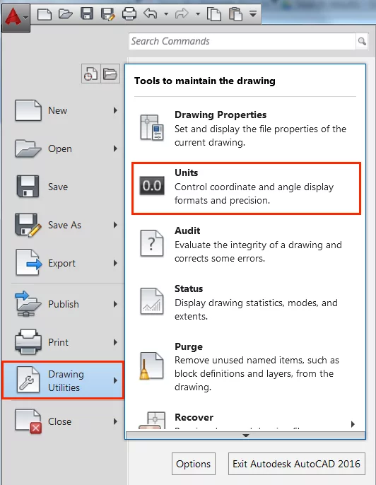
Alternatively, enter the command UNITS.
If you want to draw in metric units select “Decimal” from the Type drop-down list (A), and “Millimetres” or “Metres” within the Insertion Scale section of the Drawing Units dialogue (B).
Take care with the Architectural and Engineering length type.
This is based on feet and inches not the metric system.
Note: changing Drawing Units within the Drawing Units dialogue, does not allow you to convert objects drawn in imperial to metric or vice versa. To convert units you should consider using the -DWGUNITS↵ command or Scale tool.
Tip 1 – Using AutoCAD Templates
Save time customising drawing units when starting a drawing by using AutoCAD templates.
Use the “acad” template when you want to use imperial units, and the “acadiso” template when working in metric units.
To open an AutoCAD template select it from the Start tab when first opening the software or find it by opening a new drawing (the Big A > New > Drawing):

The “acadiso” and “acad” templates should appear in the resulting list of files as shown in the figure above (A).
If you want to start a new drawing without using a template, click the arrow contained to the right of the Open button (B). It will give you the options of “Open with no Template – Imperial” and “Open with no Template – Metric”.
Note: selecting either of the open without template options is not recommended unless you are an experienced user and have a good reason for doing so.
Step 2 – Command Window & Keyboard Shortcuts
In the early days of AutoCAD the only way to interact with the software was using the keyboard and command line.
Thankfully that is no longer the case, there is a wide selection of ribbon tabs and toolbars that you can use to find and execute commands.
However this does not mean that you should ignore the command line.
The command line is located at the bottom of model space by default, and it can be very useful when creating a drawing:
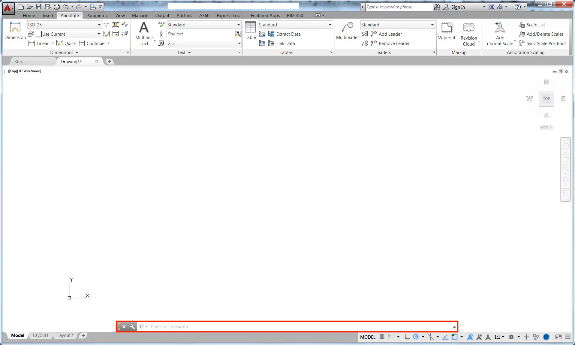
The command line is where you give AutoCAD information and where you are prompted with the next step when executing particular features of AutoCAD.
Given this working in it is highly recommended. In many cases it can be more efficient to work in the command line alone rather than in combination with ribbon tabs and toolbars.
Keyboard entered commands can save a lot of time when executing features repeatedly in AutoCAD despite being a big awkward initially when compared with using the ribbon and toolbars.
The solution to this is keyboard shortcuts; they are a shorter version of the sometimes long-winded command names. This makes them easy to master and quick to use when used repeatedly.
The table below shows some of the most useful shortcuts included within AutoCAD by default:
| Shortcut | Command | Shortcut | Command | Shortcut | Command |
| A | ARC | H | HATCH | Q | QSAVE |
| B | BLOCK | I | INSERT | R | REDRAW |
| C | CIRCLE | J | JOIN | S | STRETCH |
| D | DIMSTYLE | L | LINE | V | VIEW |
| E | ERASE | M | MOVE | W | WBLOCK |
| X | EXPLODE | T | MTEXT | Z | ZOOM |
| F | FILLET | O | OFFSET | ||
| G | GROUP | P | PAN |
Tip 2 – Increasing the Command Line Size
Increasing the size of the command line to more than the default one line makes it far more useful, especially for more complex tools.
For example, urban designers use the Align tool frequently, however it requires multiple inputs which often baffles new users.
A larger command line makes this far easier to work with.
This can be done by moving your cursor to the horizontal boundary where the Command window meets the drawing area, clicking and dragging to the required number of lines:
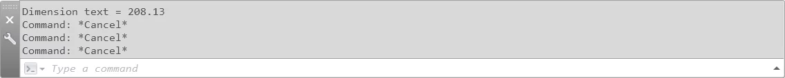
Everyone will have their own preferred depth for a command line. Personally I prefer to work with four lines.
Tip 3 – Restoring a Missing Command Line
If the Command Window has disappeared from the bottom of your model space enter Ctrl + 9 or type the command _COMMANDLINE.
Looking to get started in SharePoint instead? Check out our intro to SharePoint here.
Step 3 – Ribbon Tabs, Panels & Toolbars
First introduced as a consolidated ribbon in AutoCAD 2009, the ribbon positioned at the top of your AutoCAD window organises the many tools of AutoCAD into logical groupings.
The AutoCAD Ribbon categorises tools by tabs, and further sub-categorises tools using panels.
To prevent some panels from being overloaded with tools additional tools can be accessed by opening a drop-down dialogue box:
Most AutoCAD users are familiar with the AutoCAD Ribbon, and its intuitive user interface does not require an explanation.
However what many users may not know is that the ribbon is highly customisable.
For example, you can choose what tabs and panels to display by right-clicking on the ribbon and ticking or unticking as appropriate.
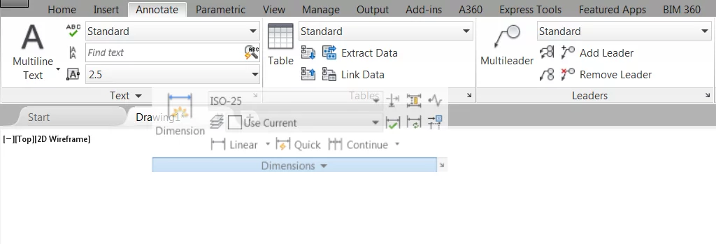
While this may not be the most ground-breaking or useful feature, one useful feature added to the Ribbon in 2010 is the ability to detach panels.
By detaching a panel it means you no longer have to navigate to it in the Ribbon, it simply sticks to your drawing space.
For example, when dimensioning buildings you no longer need to repeatedly navigate to the Annotate tab of the Ribbon.
Simply detach the required panel(s) and work with it in your drawing space until you have finished dimensioning.
To detach a panel drag it from the Ribbon. Be sure to click on a space not occupied by a button as it won’t recognise you are trying to drag a panel otherwise:
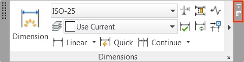
It is recommended you restore the panel once you no longer require it.
This will prevent your drawing space from becoming cluttered.
To do this click the “Return Panels to Ribbon” button located in the top-right corner of the panel:
You should also consider creating your very own panel which can save a lot of time by organising it to display all of the tools you use on a day-to-day basis.
This can be done from within the AutoCAD CUI Editor.
Tip 4 – Making Use of the Quick Access Toolbar
If you do not have the time to make a custom panel or do not believe the result justifies the time it would take to create:
Consider making use of the Quick Access Toolbar.
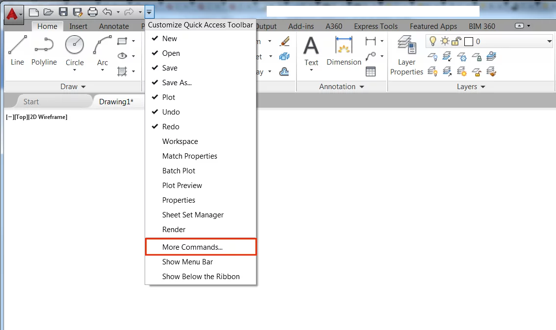
This is located above the AutoCAD ribbon and includes “New”, “Open”, “Save” and “Save As” by default.
Customise the Quick Access Toolbar by clicking on the arrow to the right of the toolbar and then selecting the “More Commands” option:
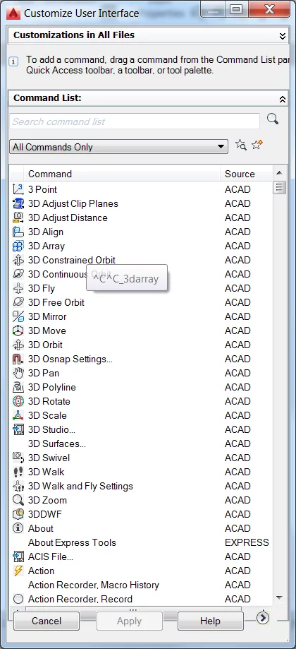
Add tools by dragging them from the Custom User Interface (CUI) dialogue to the Quick Access Toolbar:
Note: if you feel the location of the Quick Access Toolbar is not convenient or not prominent enough consider moving it below the Ribbon, directly above the drawing space.
Do so by selecting the Show Below the Ribbon option contained within the Quick Access Toolbar drop-down menu.
Step 4 – Drawing Limits & Zoom
Many people think that setting drawing limits before starting your drawing is unnecessary and an old feature of AutoCAD.
Many professionals working in the AEC can go about their day-to-day activities without doing so but setting drawing limits ensures that the zoom function works correctly.
Given that anyone working on your drawing will inevitably use this I recommend taking the time to set drawing limits.
To set up drawing limits you will need to use the command line. Type LIMITS↵.
You will be prompted to specify the limits of the lower left corner.
Set this to 0, the default limit, by hitting ↵ on your keyboard once again:

Next, enter the limits of the upper right corner as prompted within the command line. This is the important number that will determine the size of your drawing limits:
![]()
By default when working in millimetres drawing limits are set at 420 vertical (Y) by 297 horizontal (X). This is of course too small to be a building. You will most likely need to enter a number more relevant to your project requirements.
First, enter the Y coordinate separated by a comma, and then enter the X coordinate. You should notice the Y coordinate is locked by a symbol next to your cursor. It should also prompt you to enter the X coordinate of the upper right corner:
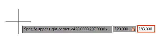
Note: in this example we have set the upper right corner limit to be 120.000 vertical (Y) by 183.000 horizontal (X), which happens to be the footprint size of the Sydney Opera House.
After you have entered a suitable X coordinate, complete the setting up of your drawing limits by hitting enter once again.
Tip 5 – Zoom Command
Quickly zoom to a required level by entering Z↵ or Zoom↵.
When prompted enter A↵ to Zoom to the drawing limits or E↵ to zoom to the extent of all objects within a drawing.
Zoom to the size of particular objects in your drawing by entering the Zoom command and entering O.
Tip 6 – Drawing Schematics
When drawing MEP schematics and the like, set your drawing limits to the size of the paper you intend to use.
Draw within these limits and will not need to resize your drawing when it comes to printing later.
Step 5 – Layer Properties Manager
Mastering layers is key to becoming an efficient AutoCAD user.
They are what stands between creating a well-crafted drawing and unorganised chaos.
Many people have learned the hard way to heed the advice to always carefully assign lines to appropriate layers.
To master layers it is first important to familiarise yourself with the Layers Properties Management dialogue.
To open the Layers Properties Management dialogue select Layer Properties from the Layers panel of the Home ribbon tab:

Alternatively, type the command LA↵.
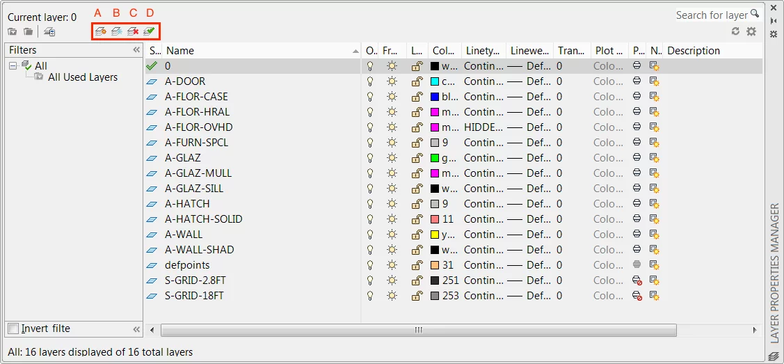
Within the Layer Properties Manager dialogue, you can find a table, which contains all of the layers and layer properties included with your drawing.
Above which there is a toolbar that includes the following essential buttons (A) Add New Layer, (B) New Layer VP Frozen in All Viewports, (C) Delete Layer, (D) Set Current:
Many people have used the Layer Management dialogue to complete simple tasks like adding and naming a new layer or changing the layer a new object is draw in.
The later is done by using the “Set Current” button or using the Layer toolbar within the Layers panel of the Home ribbon tab:

However, as well as always creating and assigning layers as appropriate, it is recommended that you make use of Layer Filters and Layer States especially for more complex drawings.
Layer Filters allow particular layers to be grouped together. Layer States allow you to restore layer properties to a predefined setup.
Tip 7 – Layer Filters
These are great when working with big complicated drawings.
If you want to see only layers with a particular characteristic select the New “Property Filter” button from the Layer Properties Management dialogue:
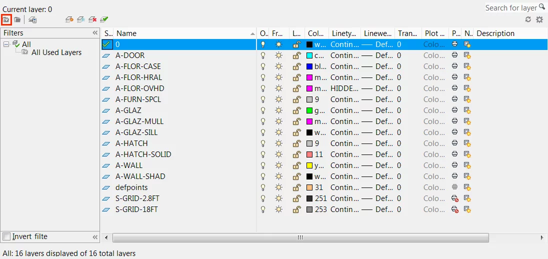
Alternatively, use the shortcut Alt + P when in the Layer Properties Management dialogue.
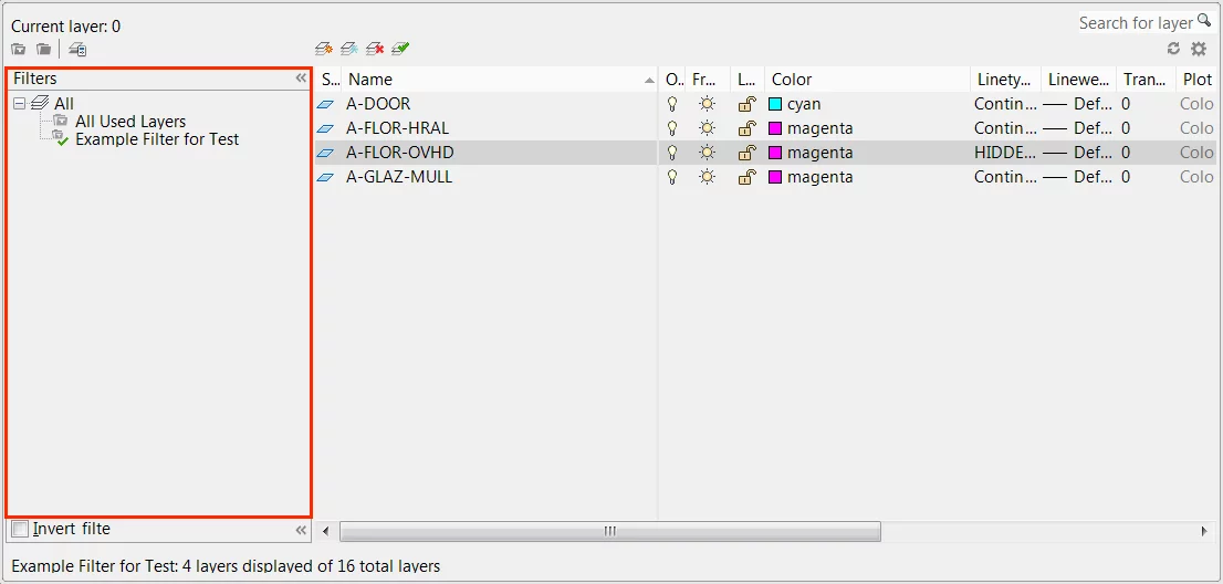
This will open the Layer Filter Properties dialogue, from which you can set up a filter to group the layers of your drawing:
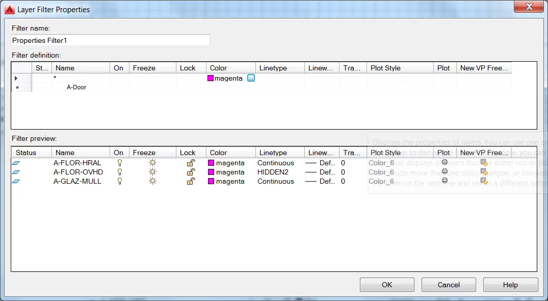
For example if you want to observe only layers that are coloured “Magenta” – select Magenta within row 1 of the Filter Definitions section of the Layer Filter Properties dialogue.
Note: use row 2, and on, if you want to create an additional filters based on other properties. For example if you want to find layers coloured Magenta as well as those named “A-Door” enter this as appropriate in the “Name” column of Row 2.
After setting up the properties you want to filter out, giving your filter a name and selecting “Save” within the Layer Filter Properties dialogue, you should be able to see only the layers that meet your criteria by selecting your newly created filter within the Filter Tree section of the Layer Properties Management dialogue:
Note: an alternative way to filter layers is to select the Group Layer button within the Layer Properties Management dialogue. Rather than automated filtering based on particular properties, the Group Layer feature allows you to drag and drop layers to newly created filter groups.
Trying to get started with Excel? Check out this great intro to Excel formulas and functions here.
Step 6 – Site Planning
Now that we have been through the basics of AutoCAD we are going to move through the typical workflow of a small-scale residential project highlighting a host of tips and tricks along the way.
This section focuses on drawing existing site conditions, and shows how you can create a reasonably accurate site plan with limited information.
Step 7 – Importing Images As A Base Layer
Often you will be given a site plan in AutoCAD format which has either been extracted from an Ordnance Survey map or a measured survey.
However, this is not always available or required.
In that event, the Image Attach feature of AutoCAD can very useful.
It can import a range of reconnaissance information such as aerial imagery, sketches and drawings.
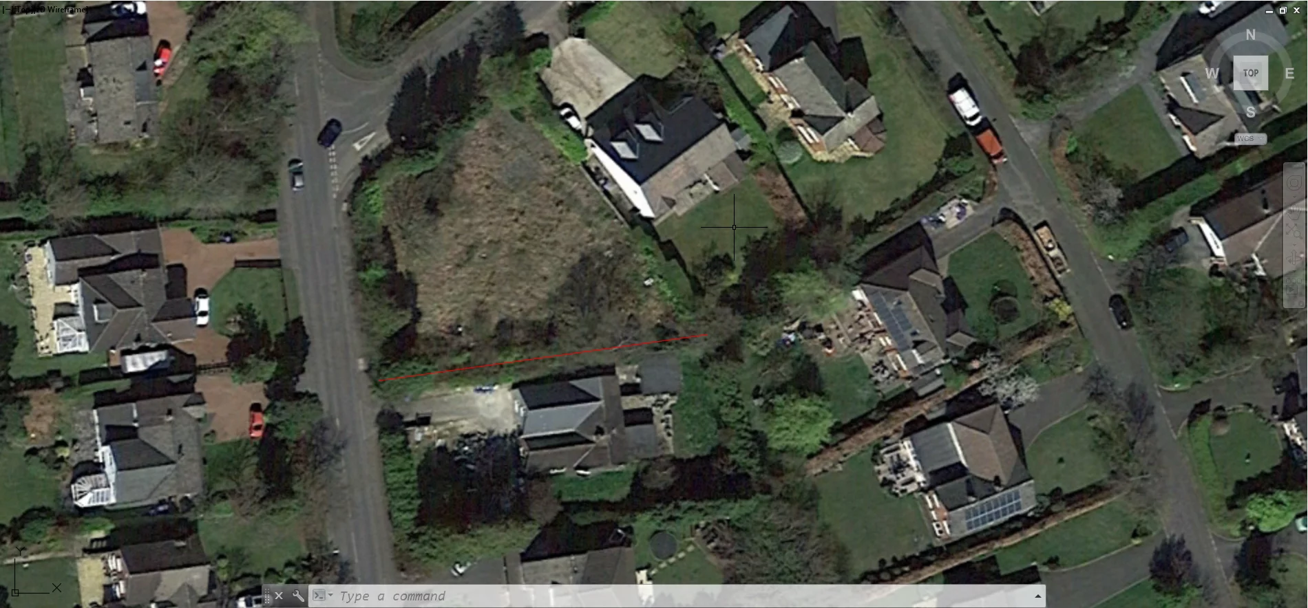
In this example we will be drawing existing site conditions using the information obtained from a land-for-sale listing as a start point:
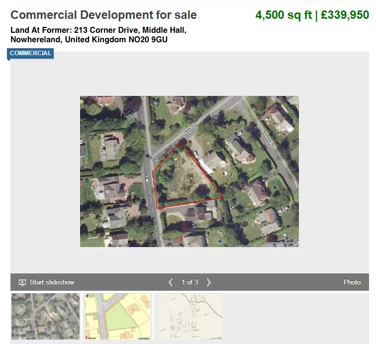
Note: some information can be determined from the land-for-sale listing such as the address, the size of the site and site boundaries.
By saving the image, showing site boundaries, to your local drive you can then import it into AutoCAD using the Image Attach feature of the software.
Do this by selecting Attach from the Reference panel of the Insert ribbon tab:

Alternatively, enter the command IMAGEATTACH↵.
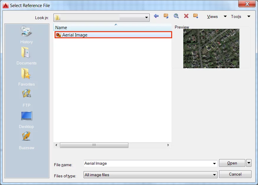
This will open the Select Reference File dialogue, from which you can navigate to the location of the locally saved image:
Note: it is recommended that you create and save images to a specific project folder, as images imported using the Image Attach feature are never actually part of the drawing.
They are imported as an external reference and AutoCAD will use the file path to find and place the image each time you open your drawing.
Therefore, if you later move or delete the image within your file explorer the path will be broken, until a newly assigned path has been set.
Once you have selected the image you wish to import from the Select Reference dialogue screen and clicked “Open”, the Attach Image dialogue should appear.
It is recommended that you set the Path Type option to “No Path”.
This will mean that so as long as the image is saved in the same folder as your AutoCAD drawing file it will be imported each time you open the drawing.
As we will be scaling the image once it is inserted, un-tick the Specify on-screen option and set the scale to 500:
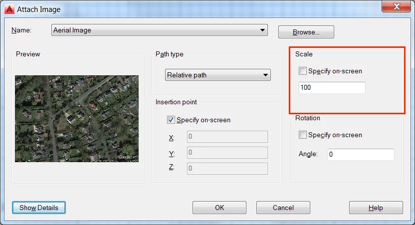
Note: the scale size is not important as we will be correcting the scale later.
Click OK to finish inserting the image. It should now appear within your drawing space.
Tip 8 – Finding Aerial Imagery
Where possible it is recommended that you take images from the source where you can obtain the largest image size possible.
In this example the size of the site with boundaries image measures 640 x 420 pixels, as such you would be better to find the site in Google Maps or similar and take your own screenshot.
Note: there are many free software programs available for taking screenshots, including Windows very own Snipping Tool, generally found within the Accessories tab of the Start menu.
Tip 9 – Adding Images to a New Layer
One of the golden rules when working in AutoCAD is to make good use of the Layers feature.
It is recommended that all images imported into a drawing are given a new layer.
This will prove useful when controlling the visibility of the image as the image is likely redundant after we have traced the existing site conditions from it.
At that point we will want to hide it more than likely.
Step 8 – Scaling Base Layer Images To Size
Once you have inserted an image into your AutoCAD drawing the next step is to resize the image to the correct size.
This can be achieved with a degree of accuracy by knowing just one real-world measurement.
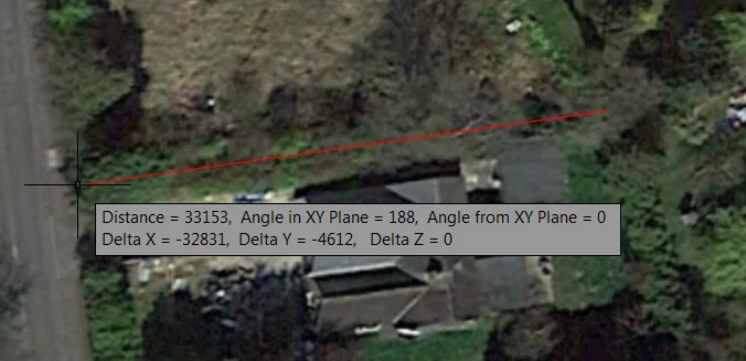
In our example let’s assume we know the length of the boundary running West to East is 44,500mm.
Begin by drawing the West to East boundary line on top of our base layer aerial image:
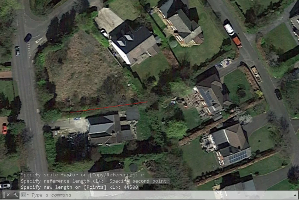
You will see that the aerial image is not to scale. In this example the boundary line we have drawn measures 33,153mm rather than 44,500mm:
The Scale tool can be used to resize the image to the correct size. First, select Scale from the Modify panel of the Home tab ribbon:

When prompted to select objects, choose the image you wish to resize. Alternatively, first select the image and type SCALE↵.
At this stage you will be prompted to specify a base point. Usually people select one of the endpoints of the line that they have just drawn as the base point.
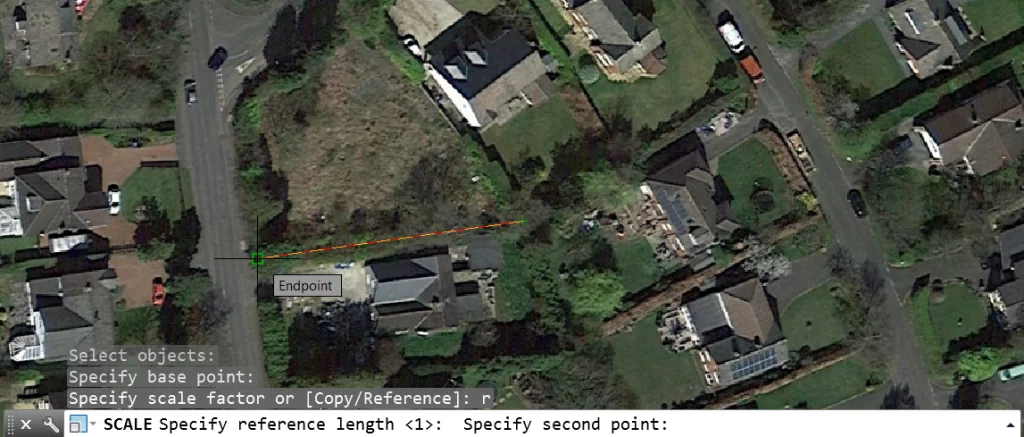
The next prompt will require you to enter a scale factor unless you choose to scale based upon a reference. As we want to scale using a reference line, type R (for reference) and hit enter:

When prompted to specify a reference length click on one of the endpoints of the reference line, you will then be prompted to specify the second point. Do this by selecting an endpoint at the other end of the line:
Complete the command by entering the known real-world length of the line, which in this case we know is 44,500mm. Don’t forget to hit enter.
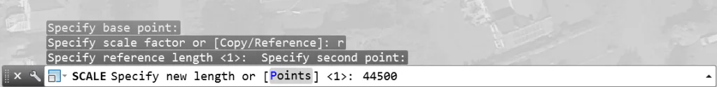
By completing this process, the image should now have been scaled appropriately. In this case, the West to East boundary now measures 44,500mm, as it does in the real-world.
Note: As in the example, you should be able to observe that the reference line has maintained the same length while the image has been resized.
You can now stretch, scale or redraw the reference line if it is to remain a feature of your drawing, as in this example, or simply delete it if you used it purely for reference purposes.
Microsoft Project is a great tool to plan out a complex project like this. Get started with this guide to Microsoft Project schedules.
Tip 10 – Determining a Known Length
In cases where a real-world length is not known, there are a number of things you can do to determine one.
Usually the best way is to install Google Earth and navigate to your site.
Using the ruler tool contained within the software you can then take a measurement of a recognisable feature.
Note: when the site boundary is not clearly defined, such as in this example due to overhanging trees or hedges, consider measuring something more definable such the length of a neighbouring building or the width of a road.
Remember, this measurement will be used as a point of reference to scale your image but can be deleted after you have done so.
Step 9 – Drawing Site Conditions
Once you have inserted your aerial image you can begin adding existing site conditions.
This can be done by tracing over the features shown in the image.
In this example, we will begin by drawing the site boundaries.
In this example, they are not clearly defined, due to overhanging hedges and trees, however for conceptual modelling this method can often prove more than accurate enough.
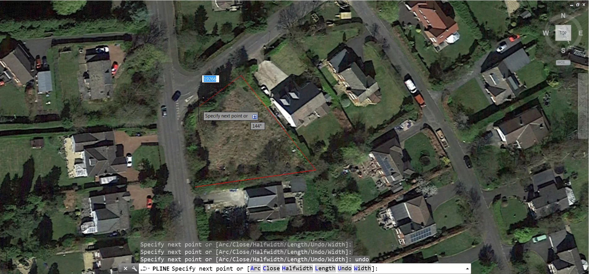
Use the Polyline tool where possible; it will allow you to create a connected sequence of segments as one single object.
The Polyline tool is found within the Draw panel of the Home tab ribbon:

Alternatively, type the command POLYLINE↵ or PL↵.
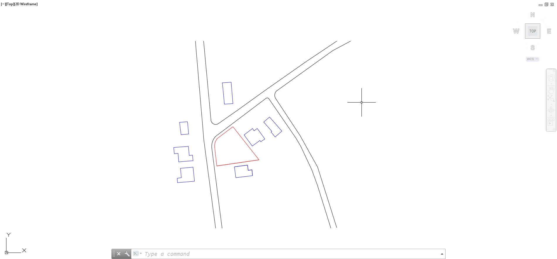
In our example, we have begun tracing the site boundary using a polyline. The process is simple, it involves specifying one point after another as you work around perimeter of the site one step at a time:
Often with site plans and boundaries you will come across features that cannot be captured by a straight line. The Polyline tool, for the most part, can handle this.
In this example, we have reached a corner that is rounded rather than angular. At this point you can switch to arc mode by typing ARC↵ or A↵:
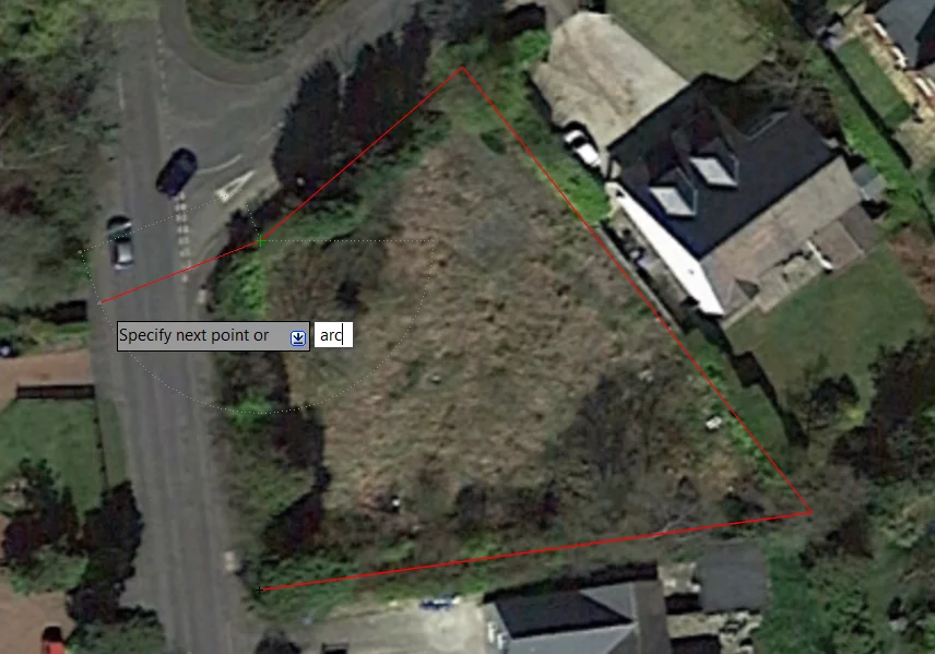
Note: you are still in the process of executing a polyline. If you make a mistake at this stage, refrain from hitting Esc and instead enter opt for undo.
Switch back to a line by typing Line↵ or L↵, and close the polyline by typing CLOSE↵ or CL↵.
Don’t worry too much if individual points aren’t exactly right they can be adjusted after you have completed the polyline.
To adjust the polyline click on it once it has been created, click on the nodes and drag as appropriate or add new nodes by left-clicking on an existing node.
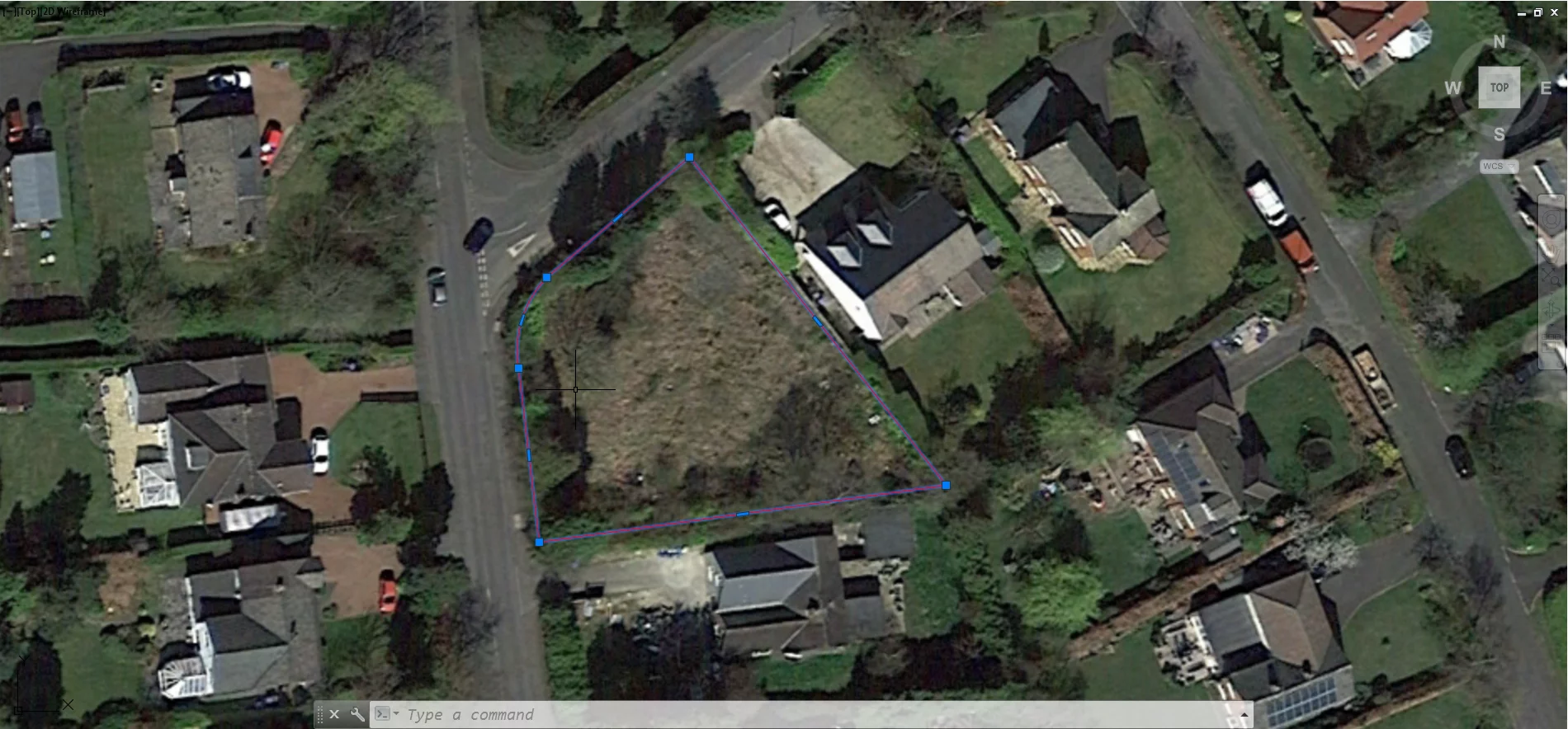
By hiding the image layer or pressing down on the mouse scroll-wheel you can see the shape you have created:
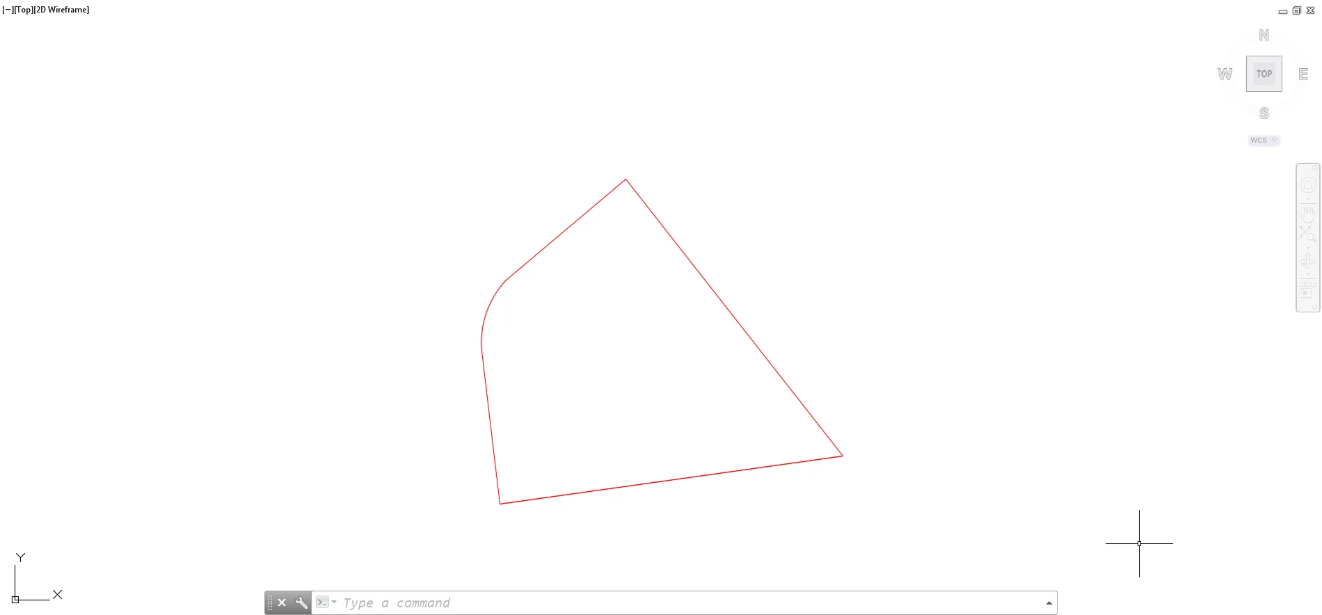
Using these basic principles you should be able to trace over many of the features that make up a site plan, fairly quickly producing something that looks like this:
Step 10 – Developing The Drawing
Now that you have prepared your site plan, lets look at developing your project further.
We’ll take a look at how you can take your organisation, management and design within AutoCAD to the next level.
Step 11 – File Management
Creating a site plan is the simple bit. Your project is about to get much more complex.
A building project, as a bare minimum, will typically consist of floor plans, roof plans, elevations, and site plans not to mention structural plans, technical detailing and interior design.
Before you begin creating all these various aspects of your project in one drawing file it is recommended that you give some thought to file management.
Good practice dictates that every elevation, floor plan, technical detail or otherwise should be drawn in a separate drawing file.
If you have not worked on a live project, this probably does not make sense.
How do you show a floor plan within a site plan if they are in separate drawing files, or create elevations by placing them side-by-side with floor plans to ensure accuracy?
The answer is external references, generally referred to as xRefs within AutoCAD. Using xRefs different drawings can be attached to a host drawing file.
This links the drawings to the host drawing without actually inserting them into the host drawing.
This system is more efficient than having all geometry in one drawing file, particularly when it comes to coordination between multiple parties.
For example, it would be difficult to coordinate a single drawing file if an architect, engineer and interior designer were all working from one drawing.
The same would apply if you were working on a site that included multiple buildings. It makes sense to have things in separate files and attach them to a host file.
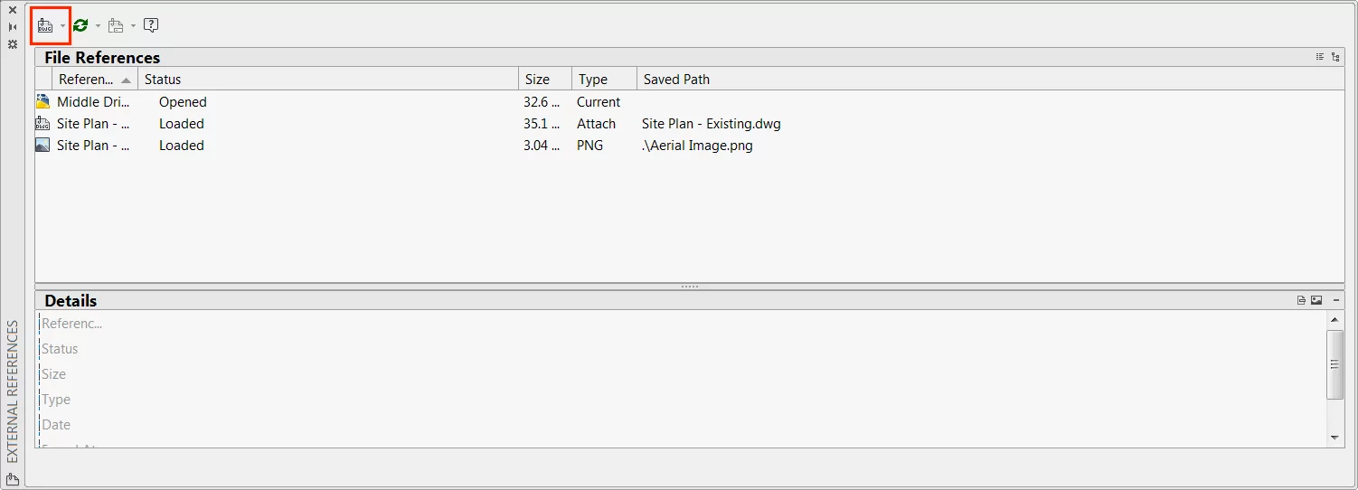
To add an xRef, select “Attach” from the Reference panel of the Insert ribbon tab and choose the file you wish to insert:

Next you will be prompted with the Attach External Reference dialogue.
It is again recommended that you set the Path Type option to “No Path”.
This will mean that so long as the image is saved within the same folder as your AutoCAD drawing file it will be imported each time you open the drawing.
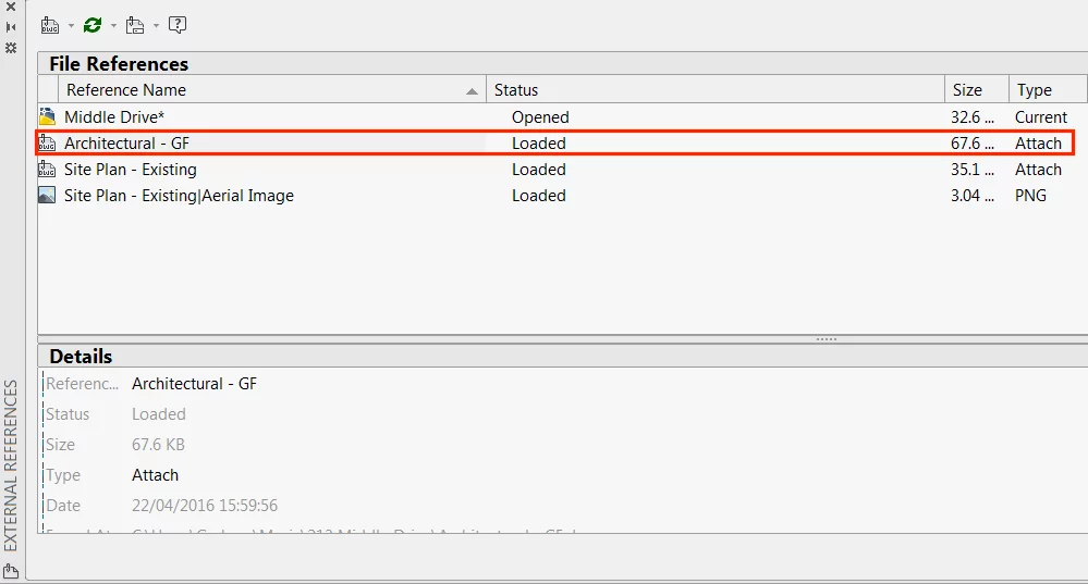
By selecting an external reference file, in this case a ground floor plan (Architectural GF), it will appear within your host drawing file:
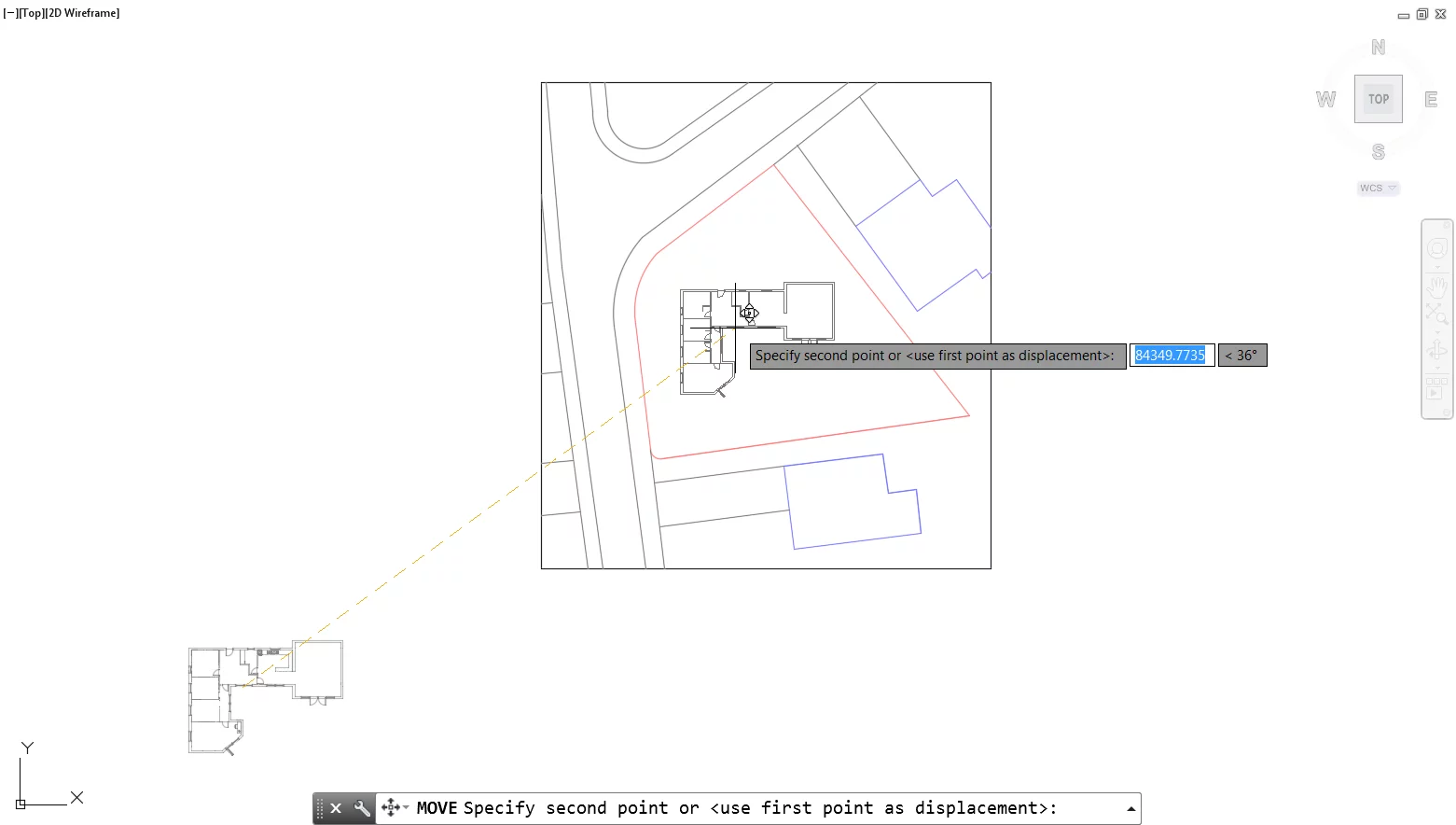
As with any other object within AutoCAD an external reference can be moved or rotated to suit the needs of the project.
In this case, we have moved it to sit on the site, and we will need to use the Align tool described in more detail later in this article to adjust its position further:
Tip 11 – Updating External References
External references are not intended to be the finished article, changes can be made to them in many ways. One way is by making changes directly to the external reference file. To do this click on the xRef and select “Open Reference” from the Edit panel of the External Reference ribbon tab:

This will open the xRef file as a separate drawing.
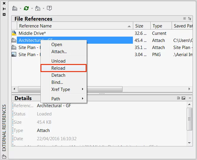
Any changes made here will need to be saved, and you will need to reload the external reference from the External Reference palette.
Do this by right-clicking on the reference and selecting “Reload”:
Note: you should refrain from renaming the external reference if possible, as a name that does not match the original external reference will mean AutoCAD cannot automatically find and reload the file.
The method of editing external references directly and then reloading them back into the main host drawing is perfect when multiple parties are working on the same project.
For example, a landscape designer may begin draughting the external arrangement once they have received a drawing containing the footprint of the building from the architect.
It can then be reloaded back into the host drawing later, without disturbing the architect’s workflow.
Other times you may just want to edit the external reference directly from the main host drawing, to do this select “Edit Reference In-Place” from the Edit panel of the External Reference ribbon tab:

Save the changes and have them reflected in the main host drawing by selecting “Save Changes” from Edit Reference Panel of the External Reference ribbon tab.
Step 12 – Layer Standards
Before you begin creating geometry, as well as paying attention to file management, good practice also dictates that we should give some time to setting-up and considering layers.
Many users find organising layers tiresome and time-consuming but rush it at their peril.
Not sticking to a well-defined layer convention, however, goes against many industry codes of practice.
Including BS1192, a UK standard that suggests CAD layers should conform to a naming convention, so as to allow information to be grouped and easily found by anybody that may wish to access it.
In the United States the National CAD Standard, suggests that layer names should be created based on a maximum of 5 data fields.
Including 2 compulsory fields: Discipline (2 characters max) and Major Group (4 characters); as well as optional fields referred to as Minor Group 1 (4 characters max), Minor Group 2 (4 characters max) and Phase (1 character max). For example:
A – Door – Full-Dims – E
<Discipline> – <Major Group> – <Minor1-Minor2> – <Phase>
Note: In this example A dictates that the layer belongs to the Architectural discipline and that its Major Group is of that of a door. The optional Minor Group 1, Minor Group 2 and Phase fields have also been completed to give an additional level of description to the layer.
Tip 12 – Sharing Layers Between Drawings
You should use the same layer standard on all of your drawings.
To save time setting this up each and every time you could transfer them to your new drawing using the DesignCenter.
The DesignCenter acts as a central location for accessing the content of all open drawings, amongst other things.
For example, if you have a drawing that you use as a template or a drawing with the layers you wish to recreate, open it alongside your current drawing.
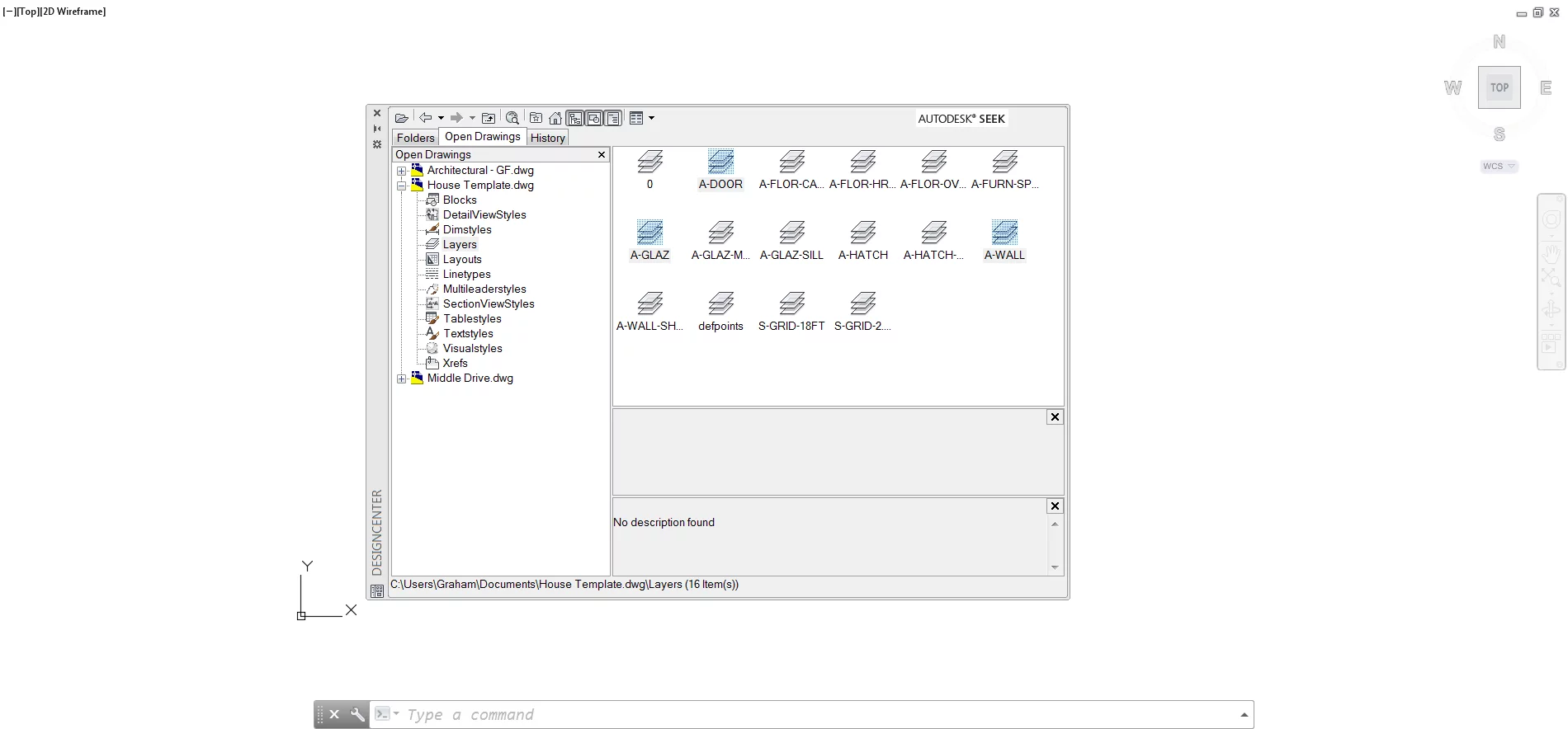
Then select DesignCenter from the Content panel of the Insert ribbon tab.

Select the Open Drawings tab from the DesignCenter dialogue (A).
By selecting the maximise toggle of the required drawing, in this case, House Template, you can find the Layers option and access all of the layers the drawing contains (B):

Select the layers you require and bring them into your current drawing by dragging them to the drawing space of the drawing you wish to insert them into:
The layers you dragged from the DesignCenter will now appear within the Layer Properties Manager palette of your current drawing, ready for use.
Tool Of The Trade
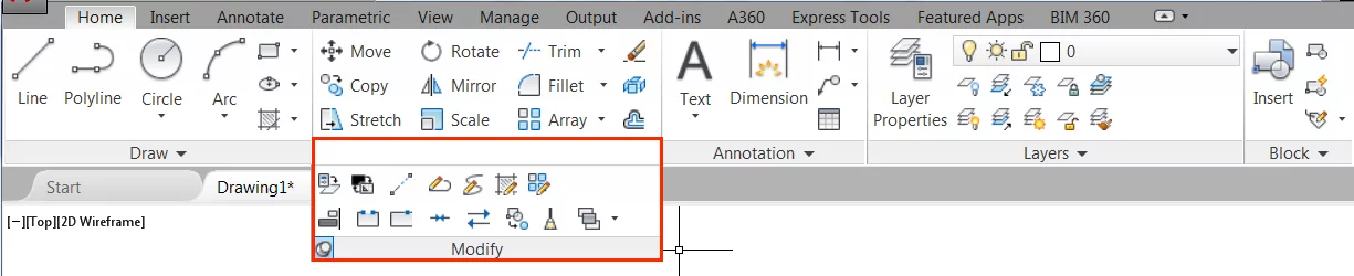
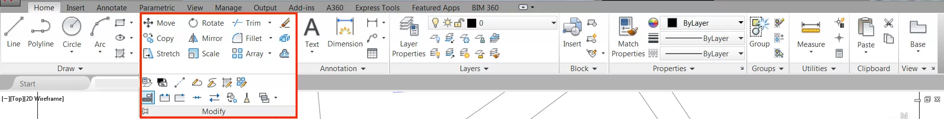
The Modify panel contained within the Home ribbon of AutoCAD is the location of many of the tools you will find useful when draughting a building in AutoCAD.
Table 2 below gives a summary of the most used tools in the Modify panel, together with relevant shortcut keys:
| Tool | Shortcut | Description |
| Offset | O | Used to offset an object at a specified distance or through a point. The offset tool is perfect for offsetting walls to the desired thickness. |
| Trim | TR | Used to cut lines to meet the edges of other lines. |
| Mirror | MI | Used to create a mirrored copy of selected objects. The mirror tool is perfect for changing the direction of door openings. |
| Align | AL | Aligns objects with other objects. The align tool is perfect for aligning building plans with site boundaries. |
| Fillet | F | Rounds or fillets the edges of two intersecting lines. |
Table 2 – Modify Panel Tools and Shortcuts
Tip 13 – Make full use of the Align Tool
Perhaps the most often overlooked tool within the Modify panel is the Align tool.
As an example, we can use it to align the Corner Drive ground floor plan xref, with the boundary line of the site plan.
To do this, first select Align from the Modify panel of the Home ribbon tab:
Note: An alternative approach is to type AL↵.
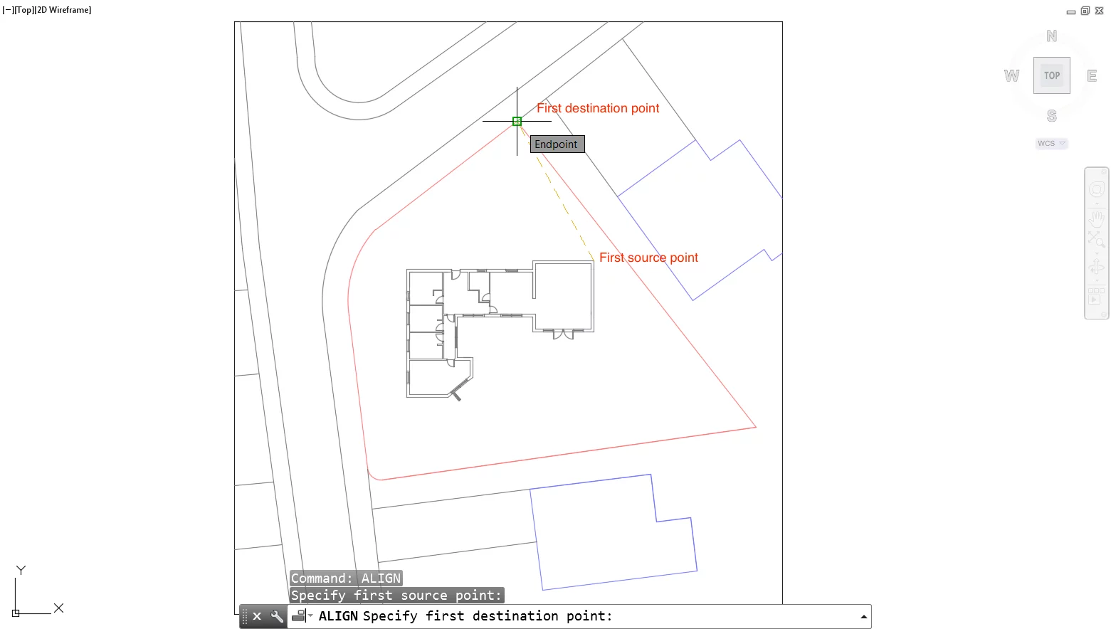
Within the command line, you will then be prompted to specify a first source point.
Do so by clicking on a particular point along the object you want to move.
In this case, a particular corner of the building, and follow this up by specifying a destination point when prompted within the command line:
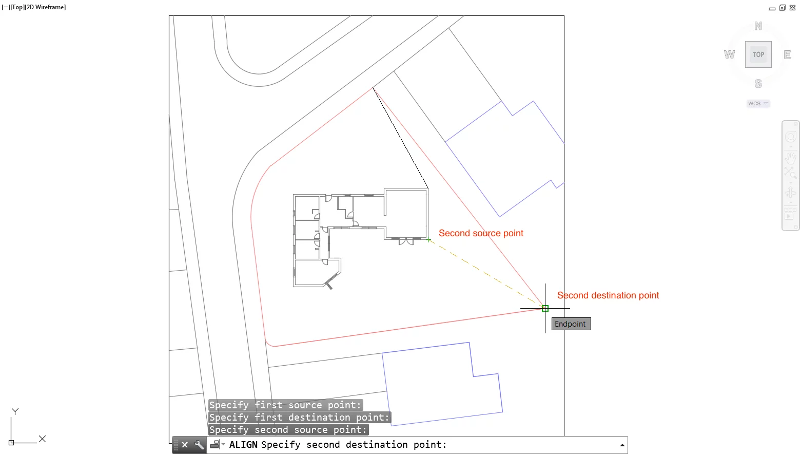
After you have specified a source point for the object you want to move and a destination point, specify the second source point and a second destination point.
In this example the second source point is the opposite corner of the building block:
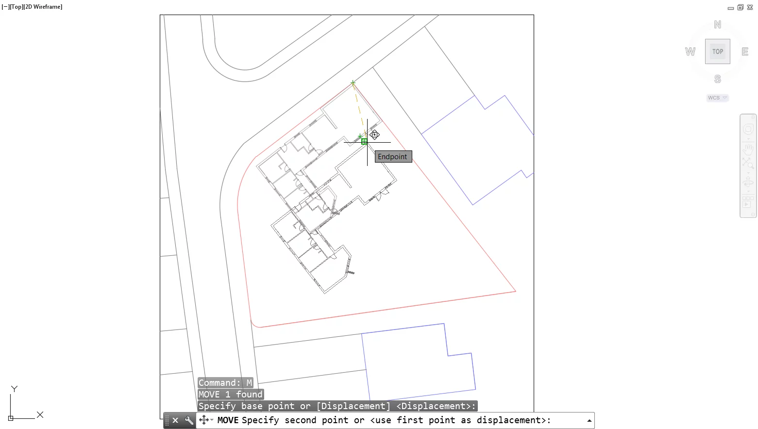
In this example the building block has now aligned itself perfectly with the boundary line of the site and we can begin to move it into position as required:
What many users do not realise about the Align tool, is that as well as aligning objects with other objects it can also be used to rotate and scale objects.
Making it possible to move, rotate and scale objects with one single command rather than individually. This can be very useful when placing doors and windows.
Rather than rotating, moving and scaling or adjusting the geometry of the door or window you can simply use the align tool as you become more familiar with how it works.
Tip 14 – Don’t Overlook the Match Properties Tool
While the DesignCenter is useful for copying layers from one drawing to another, the Match Properties tool is perfect for copying layers from one object to another within the same drawing.
Let’s assume you have been giving the task of placing objects on the correct layers. Don’t waste time on tediously clicking and changing each layer.
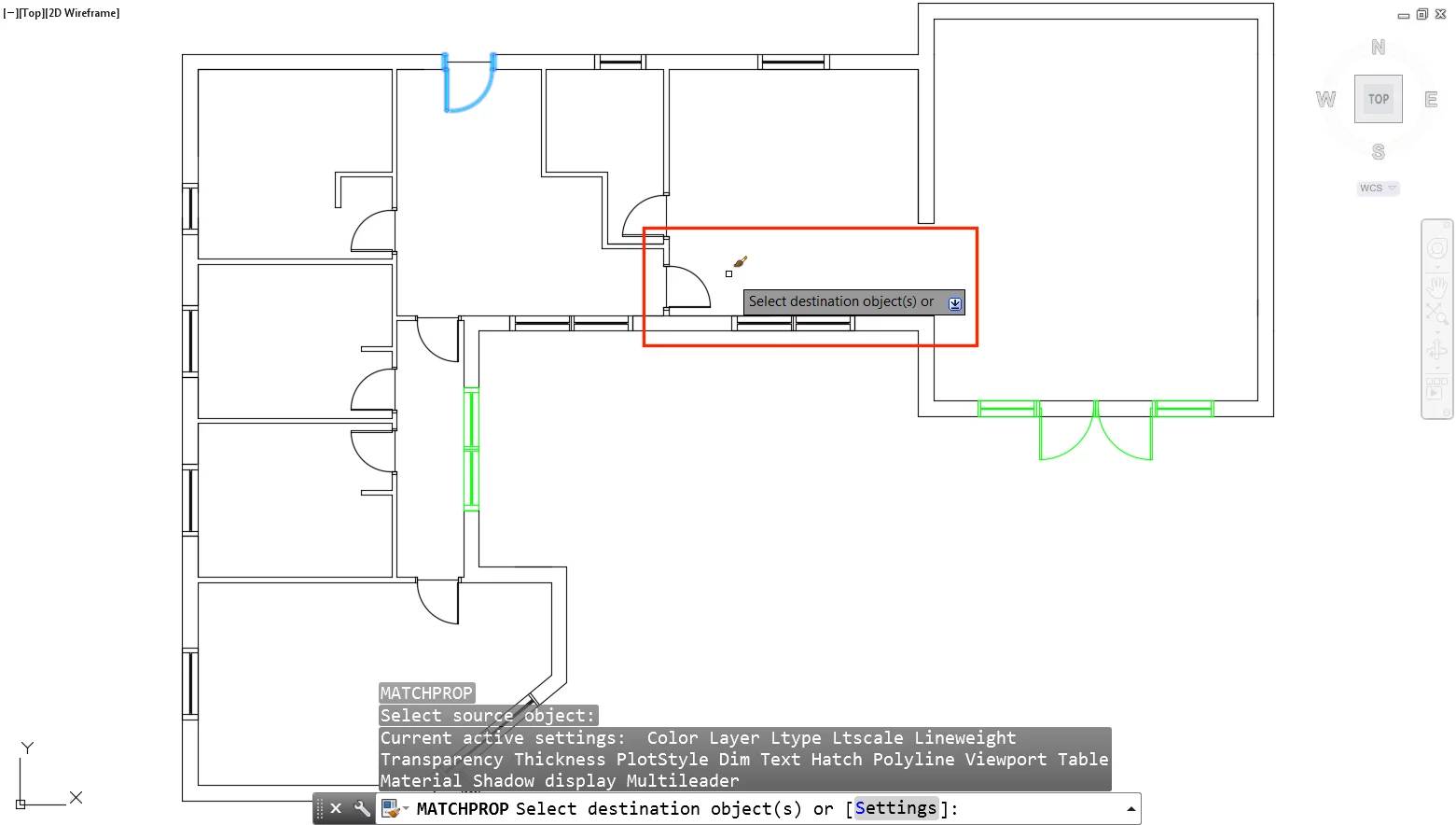
Type MA↵ and click a source object as prompted in the command line. In this case a door that is already known to be the correct layer:
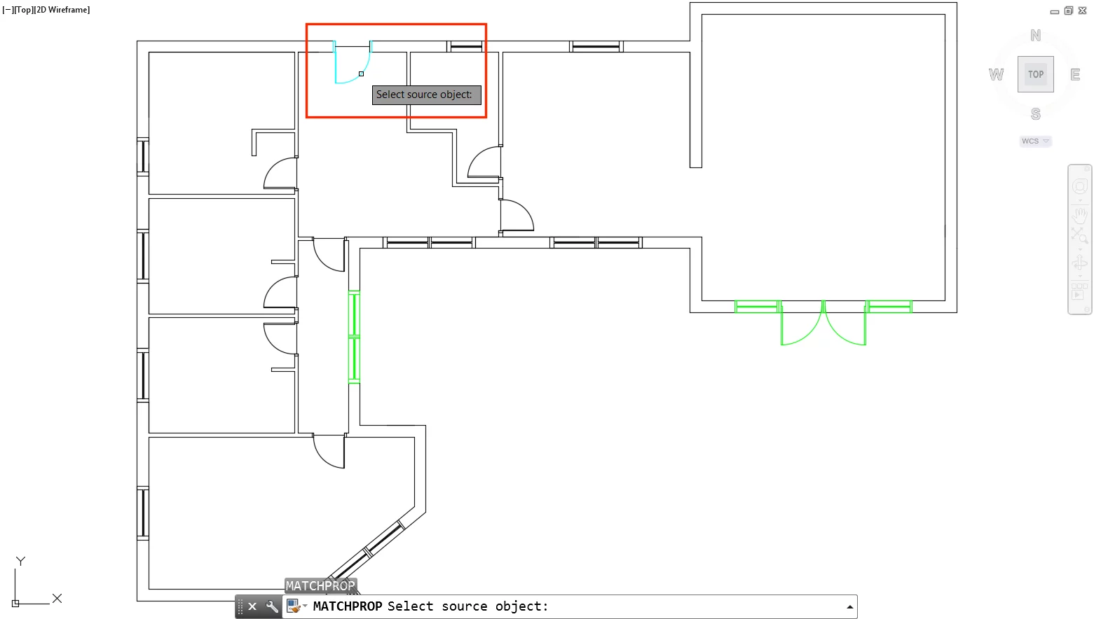
Next, click the destination objects i.e. the objects you want to change.
Notice how it matches the properties of the source object with the destination objects like for like. Now simply move around your drawing changing objects by matching them with source object:
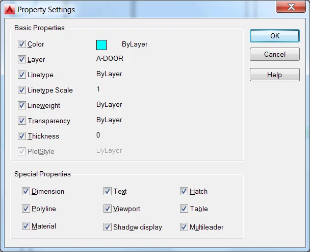
Note: If you don’t want to match all of the properties of the source object type S↵ in the command line, when MA is active, to open the Settings dialogue. From the Properties Settings dialogue you can pick the properties to be copied from the source object to the destination object:
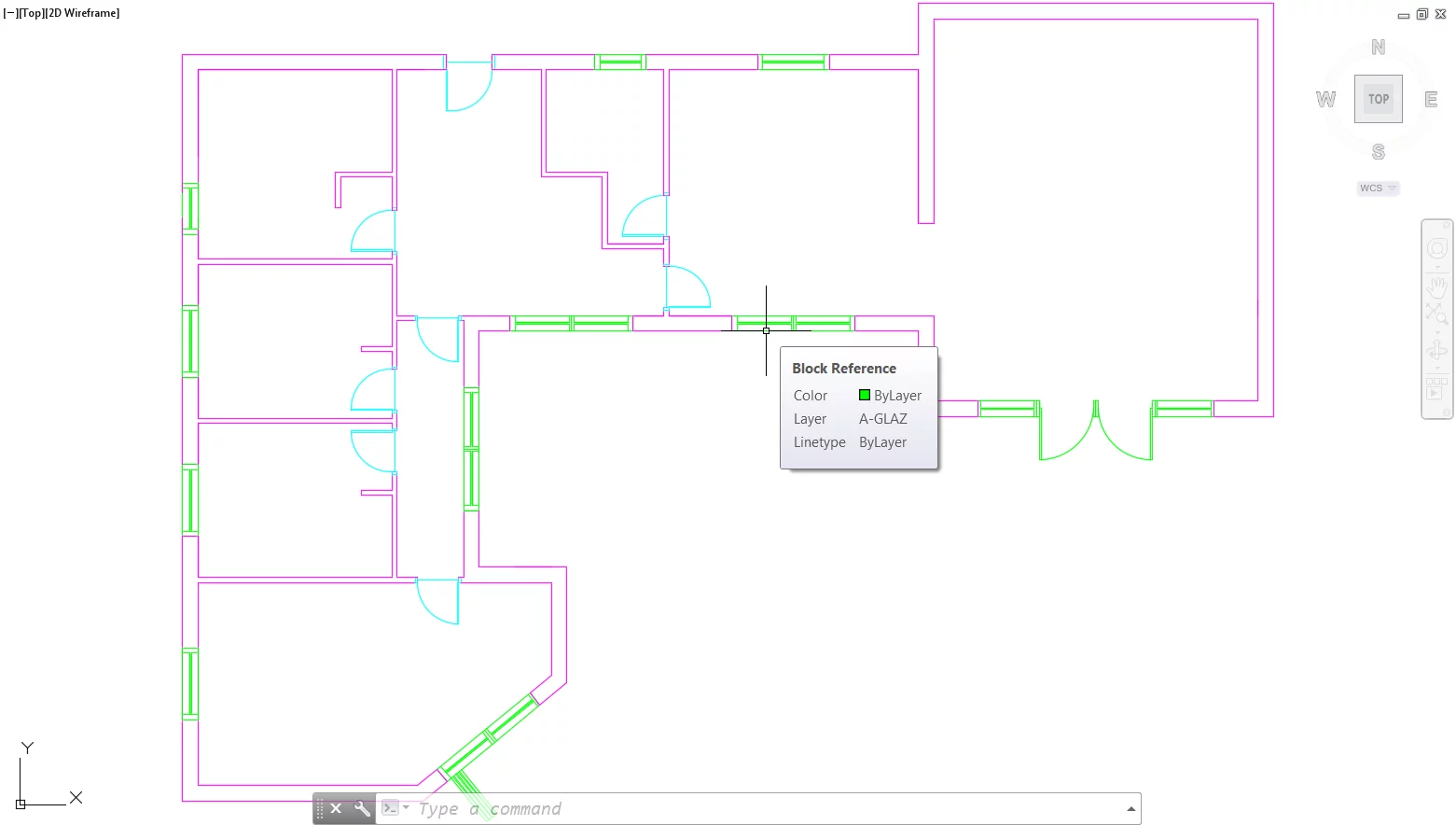
In the example of the proposed Corner Drive ground floor plan we were very quickly able to bring the layers up to scratch by using the Match Properties tool to change objects on Layer 0 to the required layer:
Step 13 – Detailing The Drawing
We have already looked at site planning and the process of developing drawings in AutoCAD.
Now we will look at some of the processes associated with populating floor plans and adding detail using hatching.
Step 14 – CAD Blocks
When detailing drawings in AutoCAD, many of us are all too fast at jumping to adding geometry without any thought for how it can be modified later.
Yes, we all want to finish a drawing faster, but this should not be at the cost of good-practice and the time later spent making modifications to your drawing later.
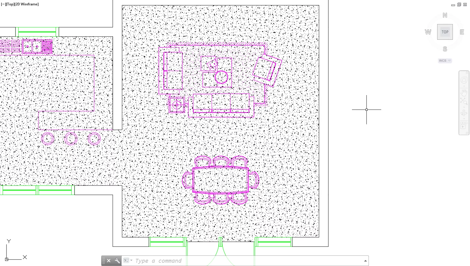
It is highly recommended that all repeatedly occurring components in a drawing be inserted as blocks. In the example project, Corner Drive, blocks have been used to populate the ground floor plan.
The doors, windows, furniture and fittings are all inserted as CAD blocks:
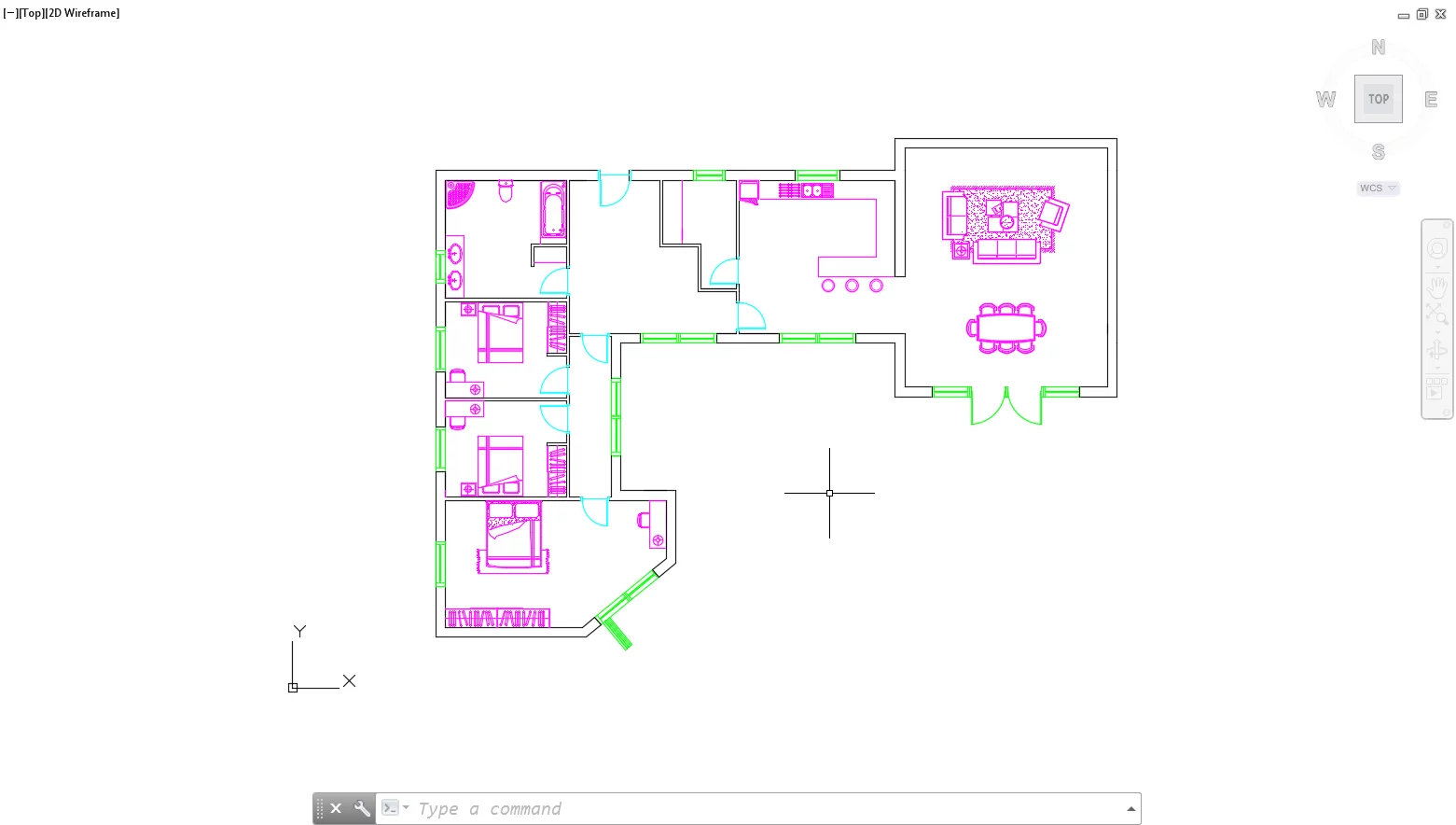
Note: The furniture was taken from an existing block library, while doors and windows blocks were modelled in place.
To model a block from scratch, first, model the geometry you would like to turn into a block. Next, select Create Block from the Block Definition Panel of the Insert ribbon tab:
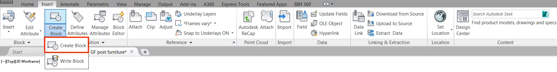
Alternatively, type the command BLOCK↵. This will open the Block Definition dialogue box:
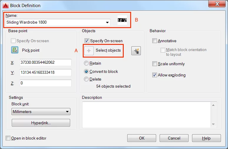
If you had not already selected the geometry you wish to turn into a block, do so by clicking on the “Select objects” button of the Block Definition dialogue box (A).
Next, give your block a name (B). In this example we have named the block “Sliding Wardrobe 1800”. However as with layers, it would be a good idea to set up a naming convention for referencing and accessibility purposes.
Note: You can now go ahead and click the OK button to create your block. Though it is recommended that you first specify a Base Point. This will make things easier when it comes to inserting blocks. The simplest way to add a Base Point is the Pick-point button (C).
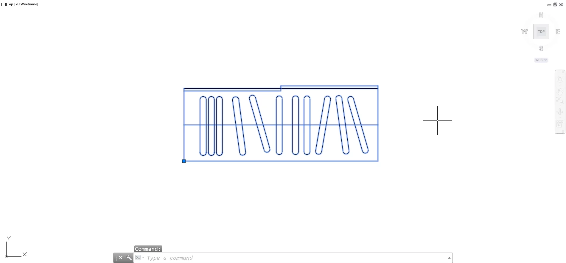
After clicking OK the block has been created. Feel free to delete the leftover geometry, which now appears as a single object when selected, or move it to the required position:
Notice how the block now features in the Insert dialogue of the Insert ribbon tab.
Add it to your drawing by selecting the “More Options” button contained within the Block panel of the Insert ribbon tab:
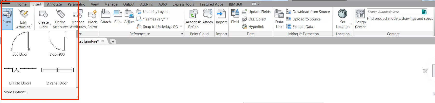
It will feature along with all of the other blocks in your drawing. Simply select it from the list and click OK within the Insert dialogue:
Tip 15 – Take Things to the Next Level with Dynamic Blocks
One of the most often overlooked features of blocks is the ability to take things to the next level and create dynamic blocks.
Dynamic Blocks, unlike the standard block, can take on a predefined level of intelligence that allows the user to quickly change the blocks visible appearance.
As an example, in the case of the Corner Drive project, the “Double Bed” block, which includes a bedside drawer has been used twice:
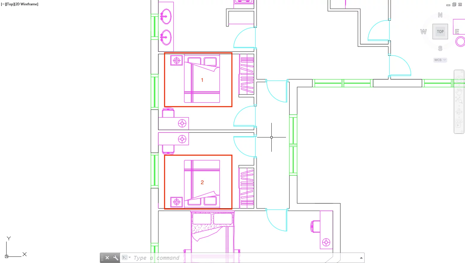
Let’s assume however that we do not want one of the beds to have a bedside drawer.
You can add a parameter that allows the user to turn on or off the visibility of the bedside drawer, thus creating a dynamic block.
Though altering the visibility of objects is among one of the most basic things you can do with a dynamic block. The table below shows what else can be achieved by creating dynamic blocks and the parameter + action(s) combinations required to do so:
| Parameter | Available Action(s) | Uses |
| Point | Move, Stretch | Move, or Stretch by selecting a predefined point of an object |
| Linear | Move, Scale, Stretch, Array | Move, Scale, Stretch, or Array based on a linear distance. |
| Polar | Move, Scale, Stretch, Polar Stretch, Array | Move, Scale, Stretch, Polar Stretch, or Array based on polar distance. |
| XY | Move, Scale, Stretch, Array | Move, Scale, Stretch, Polar Stretch, or Array at specified XY location. |
| Rotation | Rotate | Rotate to a predefined angle |
| Flip | Flip | Mirror along an axis |
| Alignment | None | Align perpendicular or tangentially to aother objects |
| Visibility | None | Turn on or off the visibility of certain objects within a block. |
| Base Point | None | Define a base point of the dynamic block. To make its use in drawing mode easier. |
Table 3 Possible Parameter + Action combinations
Note: At the most complex level dynamic blocks are a combination of parameters + actions. In the case of changing a blocks visibility, however, no action is needed and only a parameter is required.
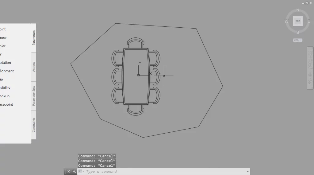
To create a dynamic block with a visibility parameter, first, open the Block Editor from the Block Definition panel of the Insert ribbon tab.
Alternatively, type the command BEDIT↵.
This will open the Block Editor mode you should notice that the background of what was the drawing space changes colour.
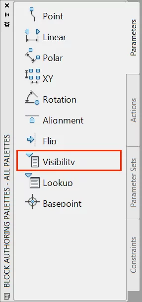
By default the Block Authoring Palette should appear to the left of the screen:
Note: If the Block Authoring Palette does not appear, select Authoring Palettes from the Manage panel of the Block Editor ribbon tab.
To add the option of changing the visibility of the double bed block, to hide/unhide the drawer, select the Visibility parameter from the Parameters tab of the Block Authoring Palette:
As prompted select the location where you would like the option for triggering visibility parameter within your drawing to appear:
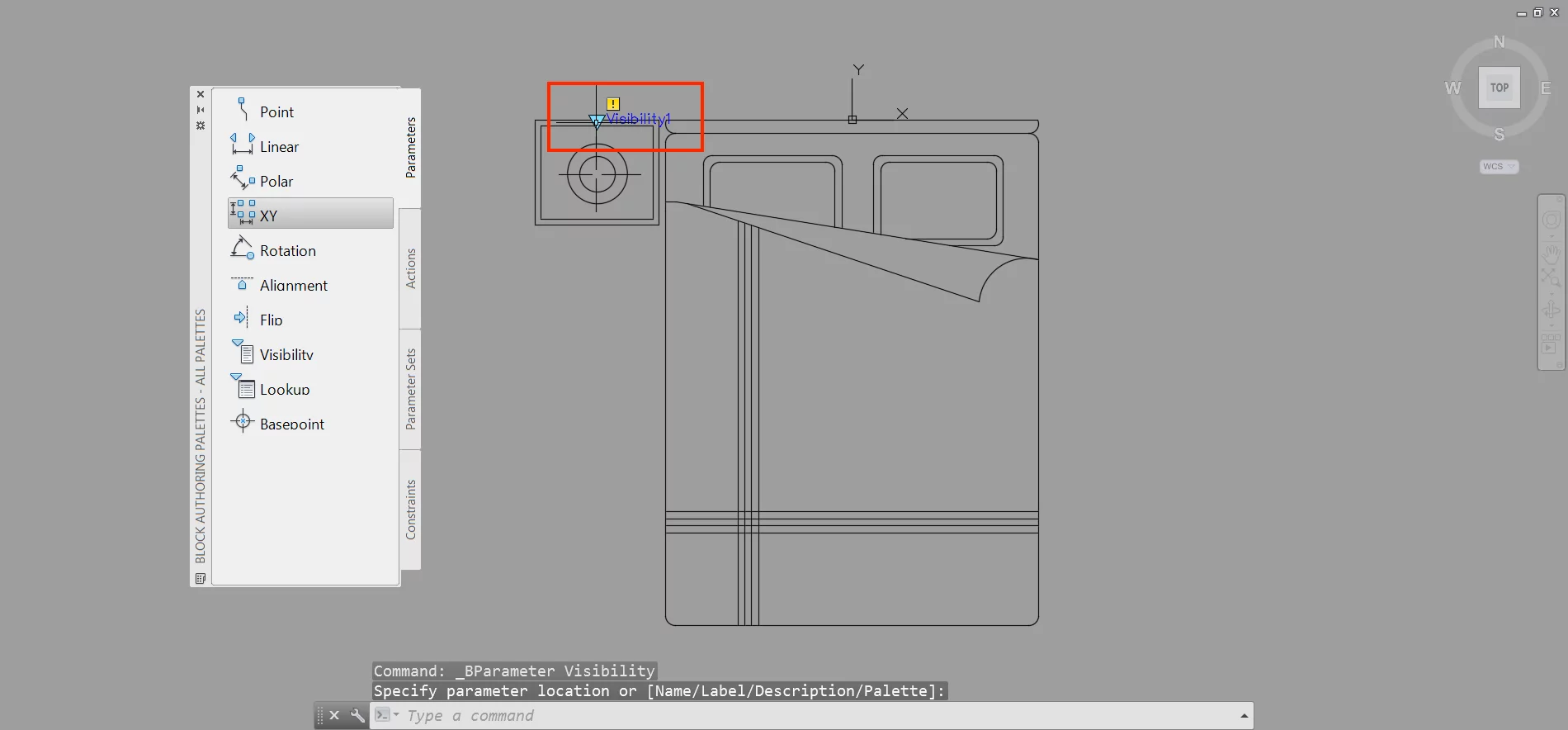
With the visibility parameter added, select “Visibility States” from the Visibility panel of the Block Editor ribbon tab:

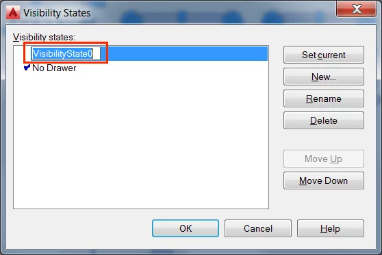
This will open the Visibility States dialogue. Add a new visibility state by selecting “New”.
Name it as appropriate in this case “No Drawer”, to indicate the drawer should not be visible.
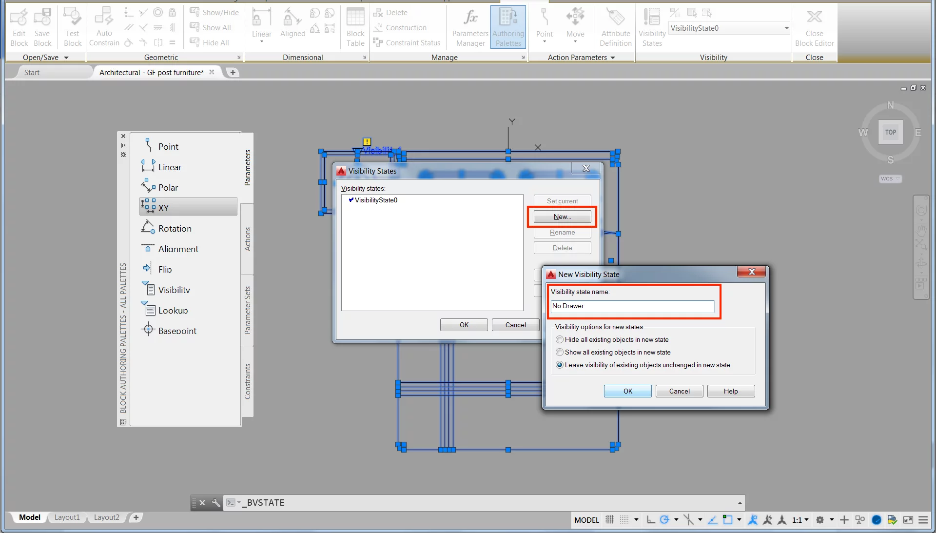
After clicking “OK” this will add the visibility state to the Visibility States dialogue. Feel free to change default VisabilityState0 to a more appropriate name and add additional visibility states as required:
The newly created state should now be set to current.
By selecting the objects you wish to hide/unhide and selecting Object Visibility, by right clicking, you can now access a number of options including “Hide for Current State”:
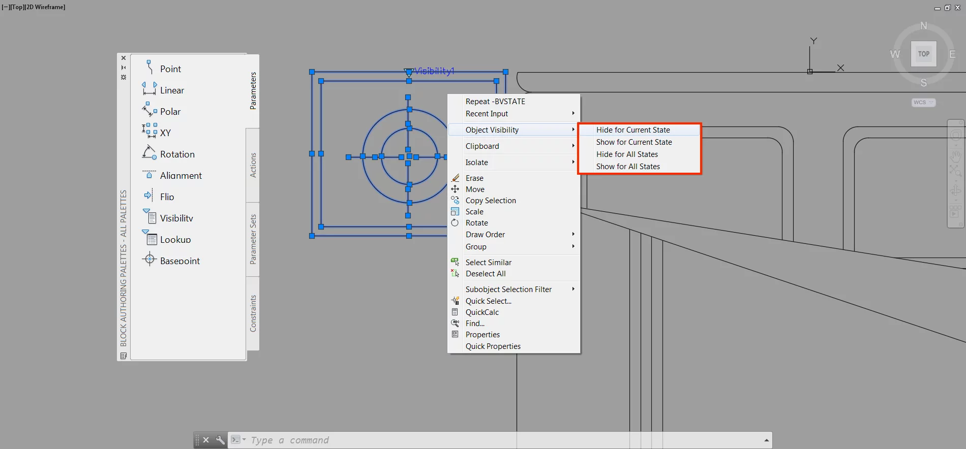
Note: The current state will have a small tick beside its name.
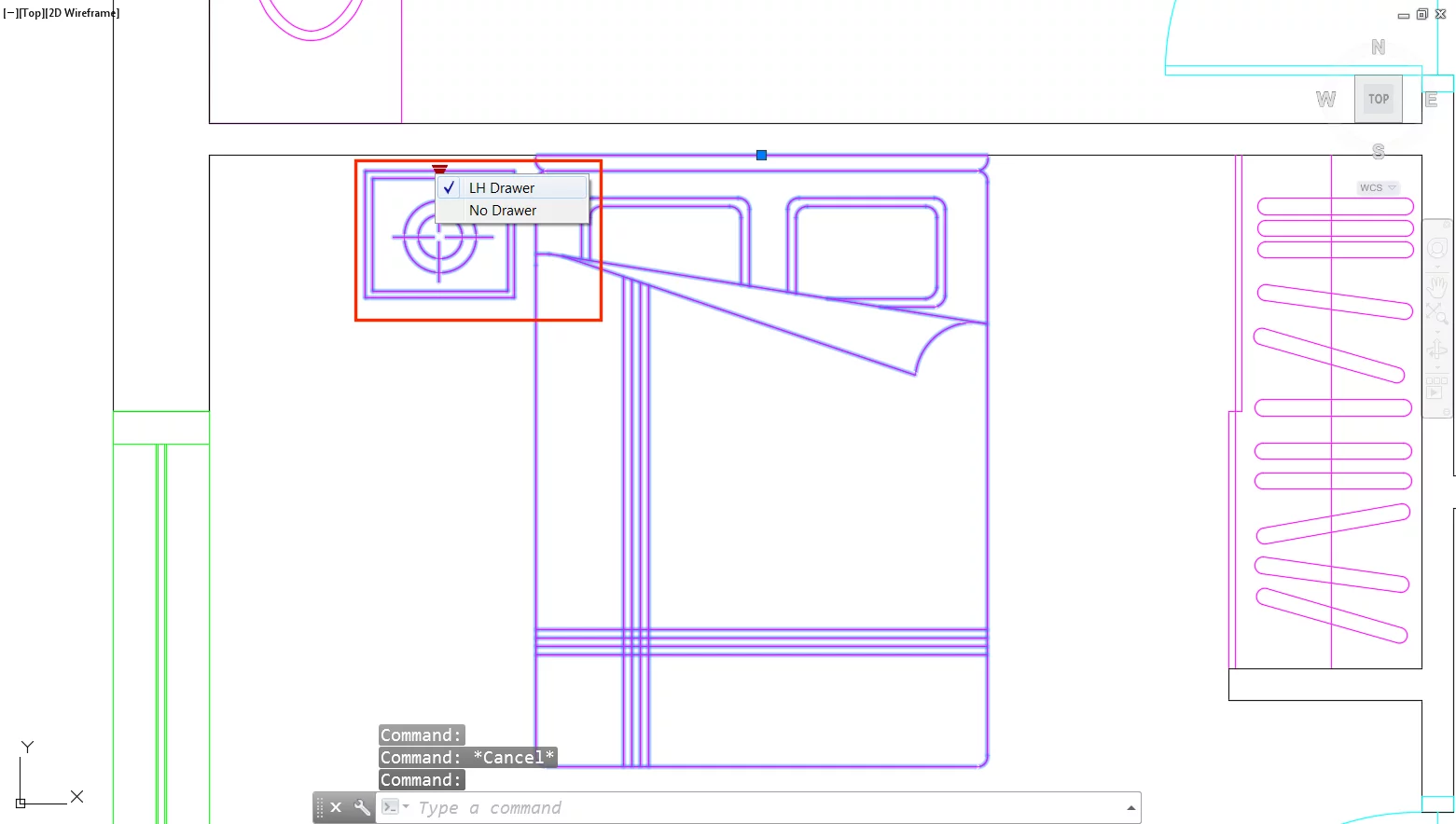
To change what state is current use the “Set Current” button in the Visibility States dialogue or select as appropriate from the drop-down menu within the Visibility panel of the Block Editor tab:

After exiting Block Editor Mode and saving the changes made, you should now be able to hide or unhide the bedside drawer by clicking on the parameter point you previously added and selecting the visibility state you created:
Tip 16 – Reduce the File Size of a Drawing using Blocks
The file size of your drawing is important, for ease of sharing the drawing you should look to ensure it does not become too large.
This is an especially important aspect when it comes to detailing the drawings of large-scale projects.
Thankfully CAD blocks help us achieve this.
By creating and inserting CAD blocks, the geometry data of a component is only stored in memory once.
When you use the block in a drawing more than once, it will require less geometry data to display the block, as the software will be able to recognise that it has already been inserted and thus knows how to handle it.
Dynamic blocks are an excellent way to reduce file size further, in particularly when using different blocks for what is only a variation of the same block.
Tip 17 – Create your Own Block Library
If you have not already begun building a block library, it is recommended that you do so.
It can be an invaluable resource, for you or your colleagues on future projects, and you can tap into throughout your career.
To save blocks externally select “Write Block” from the Block Definition panel of the Insert ribbon tab:
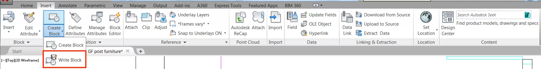
Alternatively, type the command WBLOCK↵.
Select “Block” (A) from the Write Block dialogue and choose the block you want to save from the dropdown list (B). By clicking OK the block will save to the specified location in .dwg format:
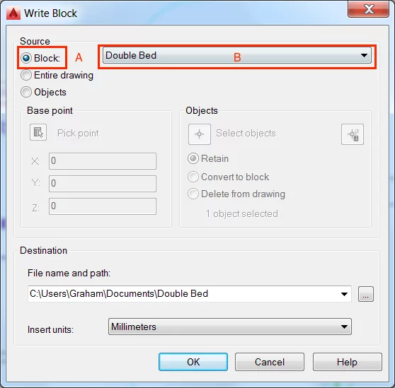
Note: Blocks saved in this way should be reinserted into other drawings using the Insert dialogue, for parameters and other block attributes to be maintained. Open the Insert dialogue by selecting Insert from the Block panel of the Insert ribbon tab or type the command INSERT↵.
Step 15 – Hatching
Hatching has long been used in architectural drawings to add detail, sadly for many though it is also one of the most frustrating features of AutoCAD.
Thankfully more recent versions of AutoCAD have aimed to simplify the process of adding hatch patterns.
Introduced as part of AutoCAD 2008, the Annotative Scale feature is one of the biggest steps towards a simplified process of adding hatches.
When enabled Annotative Scale automatically adjusts the scale of the hatch to the viewport scale.
This reduces the needed to fiddle with the scale settings of the hatch but also means when you change the viewport size your hatch scale is automatically adjusted.
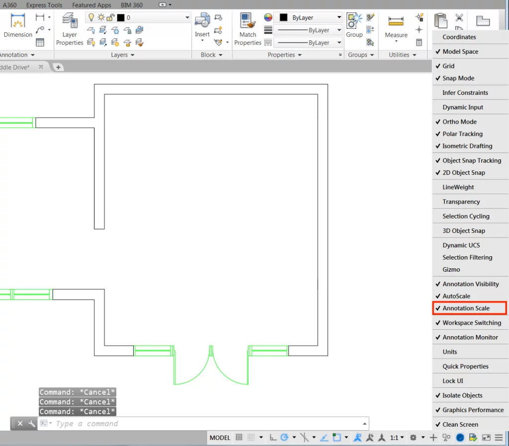
To add a hatch using the Annotative Scale feature there is, however, a few things you need to do in advance.
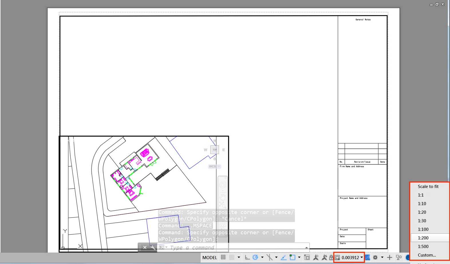
The first of which is to check that that your drawing has “Annotative Scale” enabled within the Customisation menu, contained at the bottom right of your screen:
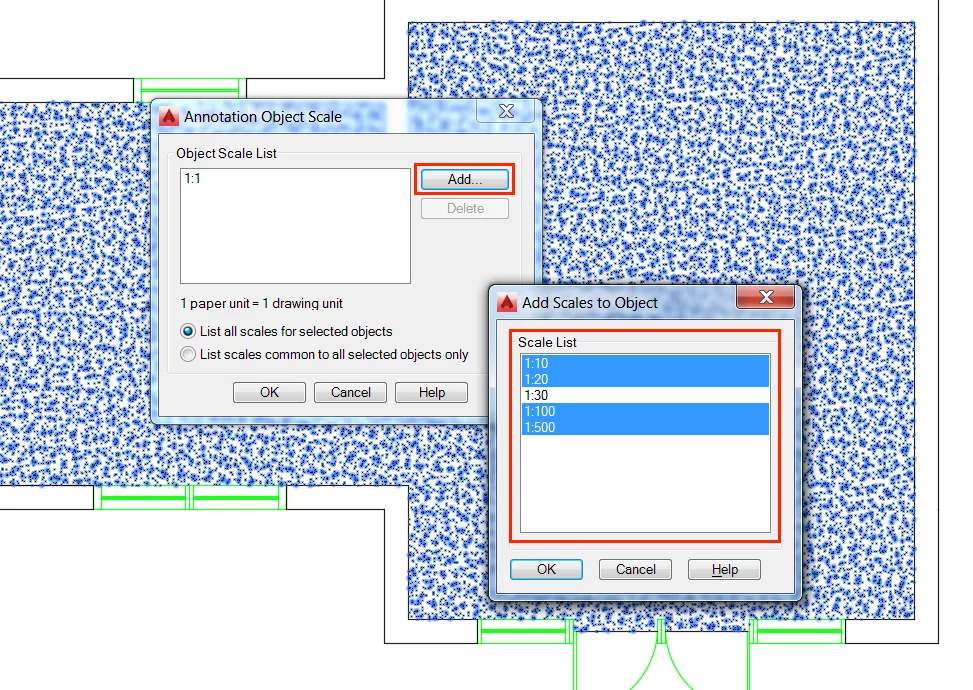
Next, make sure all of the scales you require are within the scale list of your drawing. Add any missing scales or delete unneeded scales by selecting “Custom”:

Note: Standard scales for metric architectural drawings are 1:10, 1:20, 1:50, 1:100, 1:200, 1:500, 1:1250. Others are most likely unneeded, and can be deleted.
You are now ready to add hatch patterns to your drawing.
Make sure your current scale is set to 1:1, as the scale you first draw your hatch in will be used to determine the scale factor of the hatch thereafter. 1:1 will reduce the possibility of future complications.
Next, select “Hatch” from the Draw panel of the Home ribbon tab. Alternatively, type the command HATCH↵.
Enable the Annotative Scale feature by clicking on the Annotative button, and choose the pattern you would like to add to your drawing. In this case, the pattern is AR-CONC:

Note: Because the Annotative Scale feature is enabled the scale of the hatch should look about right. If this is not the case, simply adjust the scale factor within the Properties panel of the Hatch Creation ribbon tab.
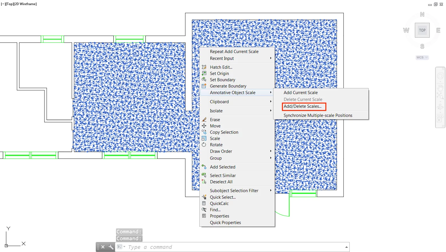
Now that the hatch pattern has been added to your drawing we need to define what viewport scales that you want it to automatically adjust to.
To do this right click on the hatch and select “Annotative Object Scale”. The option of “Add/Delete Scales” should be available:
Now when you adjust the viewport scale this will adjust the hatch scale.
If the hatch scale is not suitable adjust it accordingly within the Properties panel of the Hatch Editor ribbon tab. Alternatively, type the command HATCHEDIT↵.
Note: thanks to Annotative Scale when you change the hatch scale, it will now only change in the current viewport scale. Meaning there is no need to set up layer views or continually tinker with the scale of drawings.
Tip 18 – Make your own Hatch Pattern
Alternatively, type the command SUPERHATCH↵.
As well as being an excellent way to create a new hatch pattern, which you will need to insert as a block, Super Hatch also allows you to hatch using an image.
Hatching using an image is perfect for those of us that like to go the extra mile when creating floor plans and other drawings.
By using it, you can quickly add images to give a more realistic idea of floor finishes. For example, let’s assume you wanted to add a photo realistic concrete texture to your floor plan.
First, select “Image” from the Super Hatch dialogue.
Next, specify the image you would like to insert. After clicking through the Attach Image dialogue you will be prompted to specify the lower left insertion point of the image (A), followed by the scale factor (B):
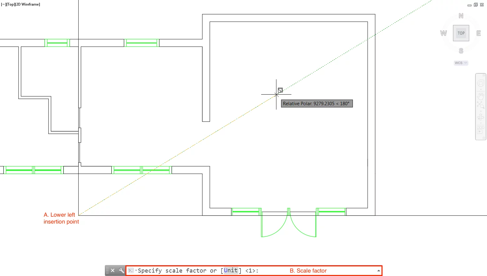
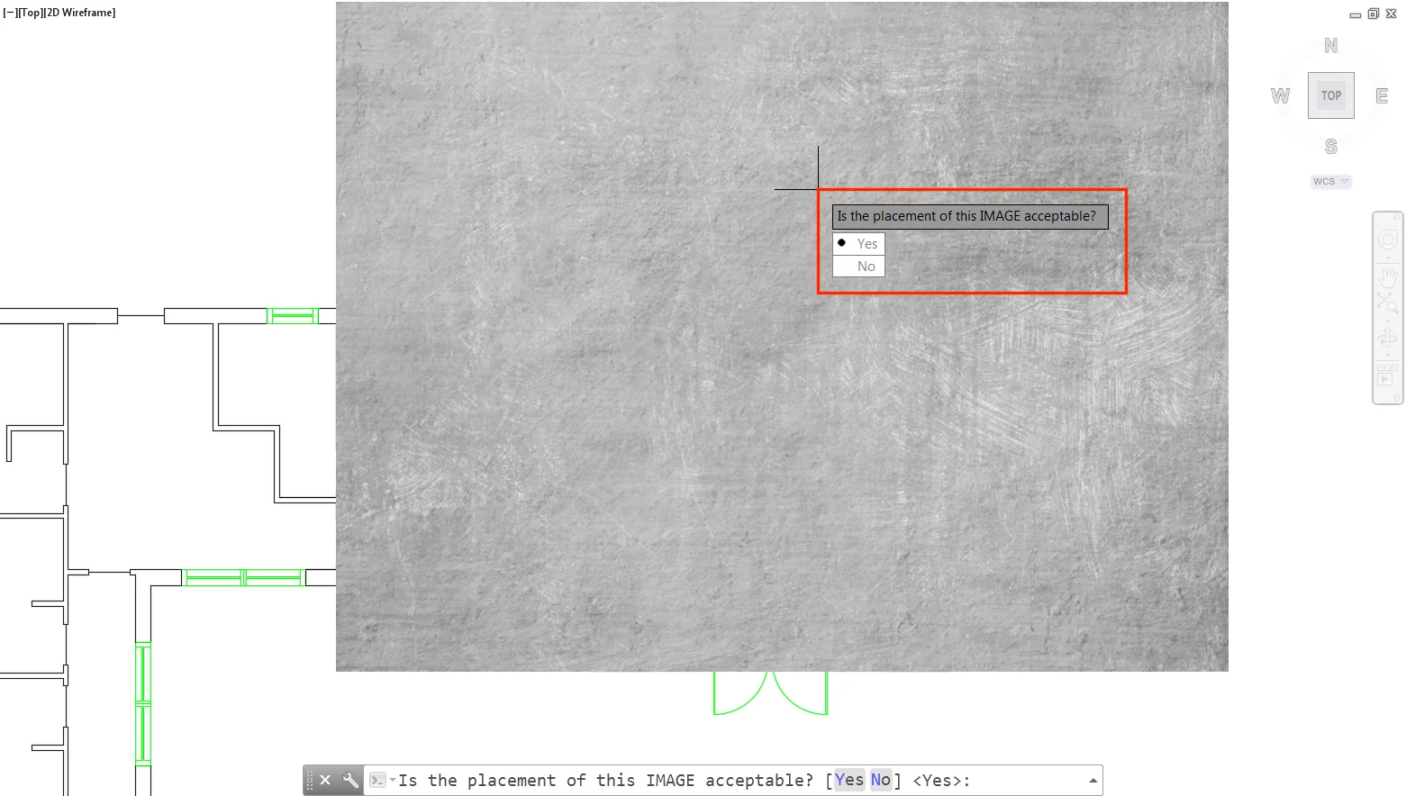
In this case, the image scale is 30. As this is enough to fill the living room floor space comfortably, without stretching the image too much. If you are satisfied with the placement type Y:
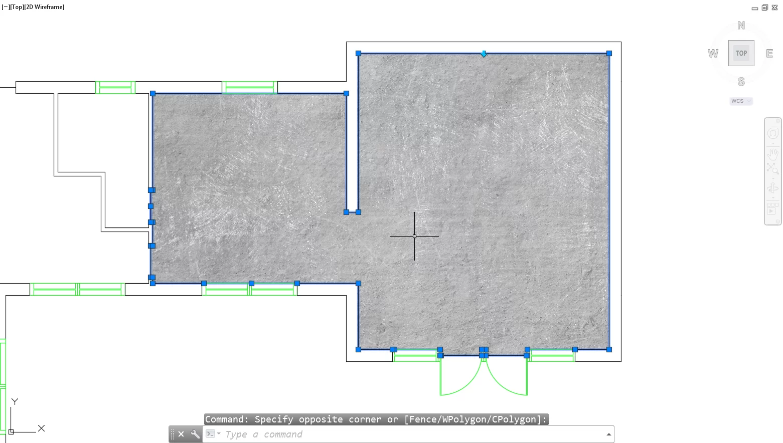
When prompted select the area you would like to hatch. Don’t be put off by an error message that may read “Error analysing internal islands” at this stage. This is often irrelevant, and you can proceed to confirm the internal point you have selected:
Tip 19 – Set Up Default Hatch Settings
There are numerous steps we repeatedly take when adding hatch patterns to our drawings one of which is setting the draw order of hatches.
Some users will relate to continually changing the draw order of hatches so that they appear at the back of the drawing:
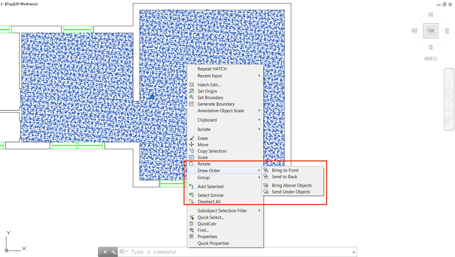
To do this type HPDRAWORDER↵. Enter a value of 1 to indicate that you always want the hatch to be sent to the back.
Tip 20 – Filling the Background of CAD Blocks
You may often create floor plans and other drawings that you would like to hatch but also add, for example, furniture blocks to.
This creates the dilemma of hatches appearing behind furniture blocks in a way that reduces legibility and ruins the visible appearance of your drawing:
The solution here is to fill the background of the CAD block. This alone however can be tricky when CAD blocks are complex.
One of the simplest ways is to do this is to use the boundary tool to your advantage.
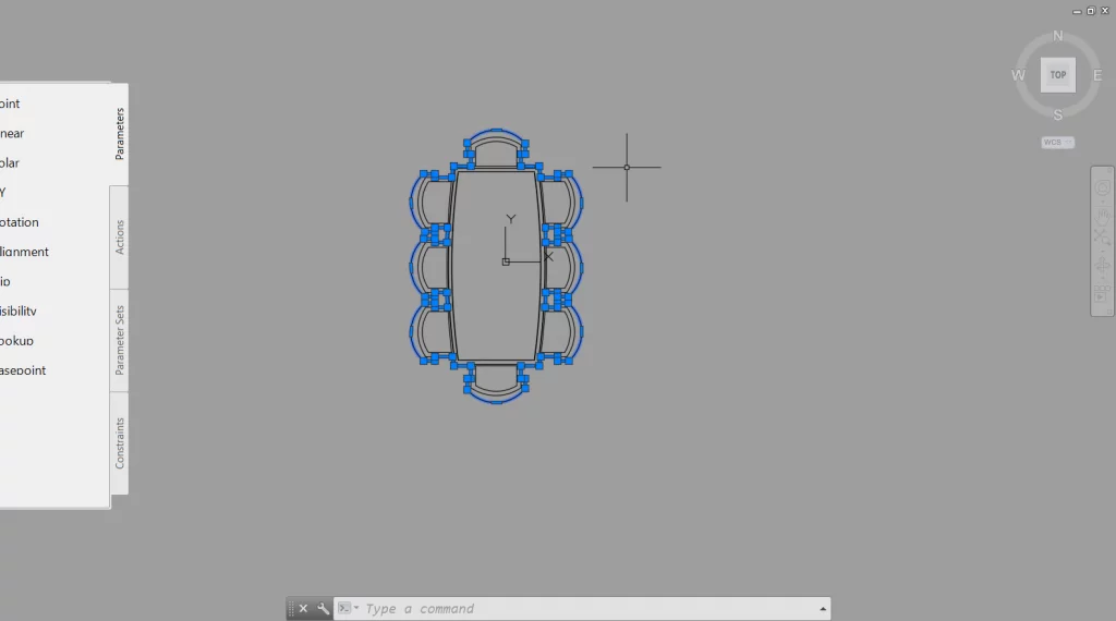
First, open the block within the Block Editor, and next draw a closed line around the extent of your block:
With the closed line drawn. Type BOUNDARY↵, and make sure the type is set to “polyline”. Click an area between the block and the closed line. This will create a polyline around the CAD block. Feel free to delete the outer boundary edge this is no longer needed:
The block is most likely drawn on Layer 0. Place the newly created polyline on a different layer and turn off layer 0. You should now be left with only the outline of the block:
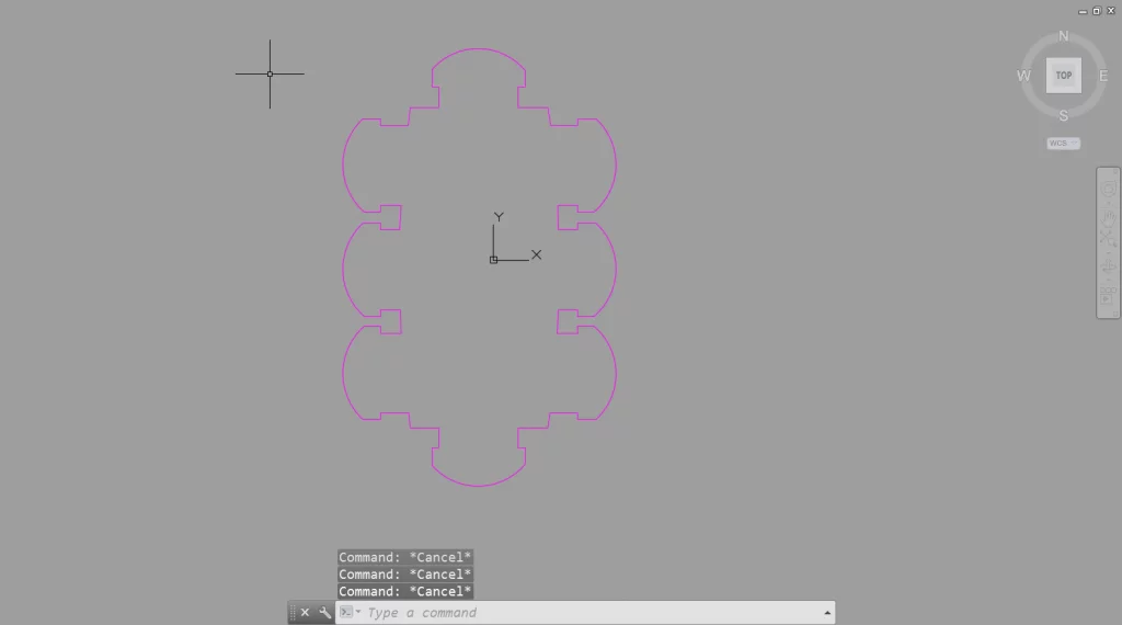
Apply a solid hatch to the inside of the polyline and colour this 255, 255, 255.
This should appear perfectly white, and not be a noticeable off shade of white when printing.
Turn layer 0 back on, and delete the polyline you used to find the outline of the block:
The block should now have a background that you cannot visibly see through. If this is not the case, you may need to make sure the draw order of the hatch pattern is set to back.
Note: Using the hatch pattern to fill the background of blocks in this way is often more effective than using the wipeout tool. As wipeouts are known to contribute to problems when it comes to printing.
Step 16 – Plotting
Often the most frustrating aspect of AutoCAD that users find is when it comes to printing a drawing or exporting it to PDF. Let’s establish how to set up a drawing successfully for plotting, using the Corner Drive project as an example.
Want to get into Microsoft Word? Read our guide on paragraph formatting in Microsoft Word here!
Step 17 – Layout Views & Page Sizes
When using AutoCAD, it is important to remember there are two working environments at your disposal. Including model space, and paper space.
To get your drawing(s) out of AutoCAD, you are going to want to place them on a page.
To do this it is recommended that you use paper space where you can set things to the defined paper size you wish to plot at.
In recent versions of AutoCAD paper space can be accessed by hovering over the window tab bar. The option of Layout 1 should already be available.
An equally fitting name for Layout 1 could be Page 1, as each of the layout views you create generally represent different pages or sheets.
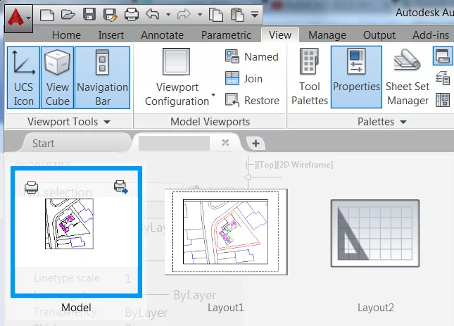
When you enter paper space, in this case, Layout 1, don’t worry if your drawing is not there are shown how you want it to display.
The first thing you should look to do is set the paper size. To do this select Page Setup from the Layout panel of the Layout ribbon tab:

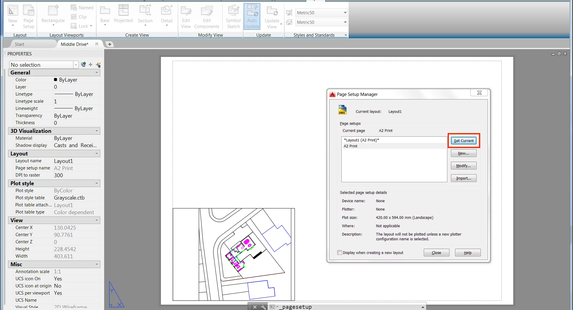
At this stage it is recommended that you create a new page setup. To do this click “New” within the Page Setup Manager dialogue:
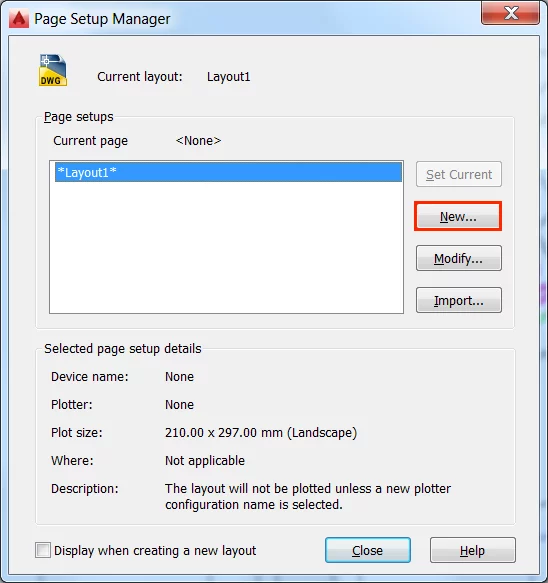
Name the sheet as you see relevant. In this case, we are going to set up a page for print at A2 size, so we have called our page setup “A2 print”.
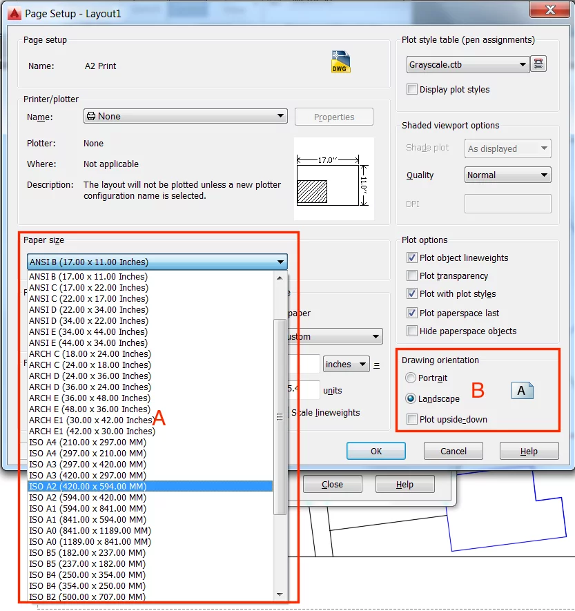
When you click OK, this will open the Page Set dialogue, and from here the desired paper size can be selected (A). Be sure to set the orientation to landscape or portrait depending on your requirements (B):
Once you click OK, the page the page setup will be saved and added to the Page Setup Manager Dialogue. Select your newly created page setup and click the “Set Current” option.
You should notice the page size change:
Tip 21 – Set up Page Templates
While you are within the Page Setup Manager, why not go ahead and create page setups for all of the printing sizes you intend to use in the future.
In the AEC industry, this probably means all standard sizes from A3 to A0.
Once you have created a page setup for each of them they can be quickly imported using the Import option, found within the Page Setup Manager.
Step 18 – Title Blocks & Viewports
Once you have your layout view set to the required page size, you will need to add a title block. Title blocks are essential in the AEC industry as they allow us to convey key pieces of information relating to the drawing.
To add a title block, you should have this already made within another file in .dwg format. Insert it by selecting “More options” from the Block panel of the Insert ribbon tab:
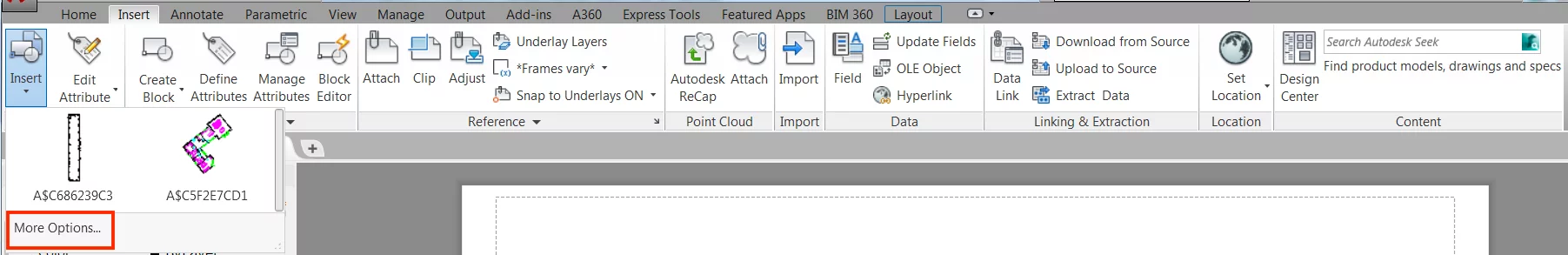
Alternatively enter the INSERT↵ command.
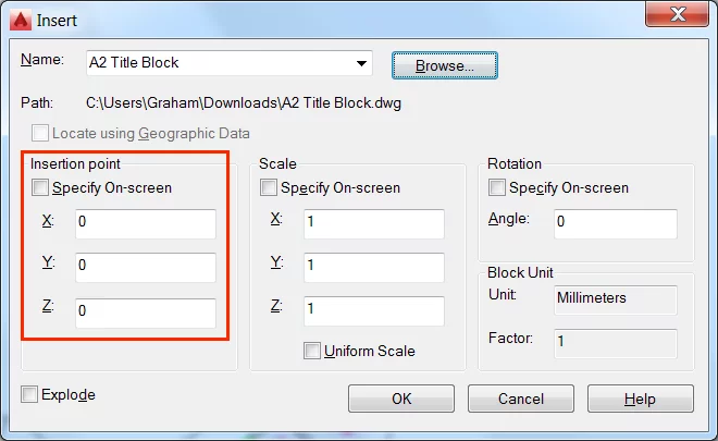
Navigate to the desired file from the resulting dialogue.
You can choose to specify its insertion point within the Insert dialogue if you setup your title block ready to take this into consideration:
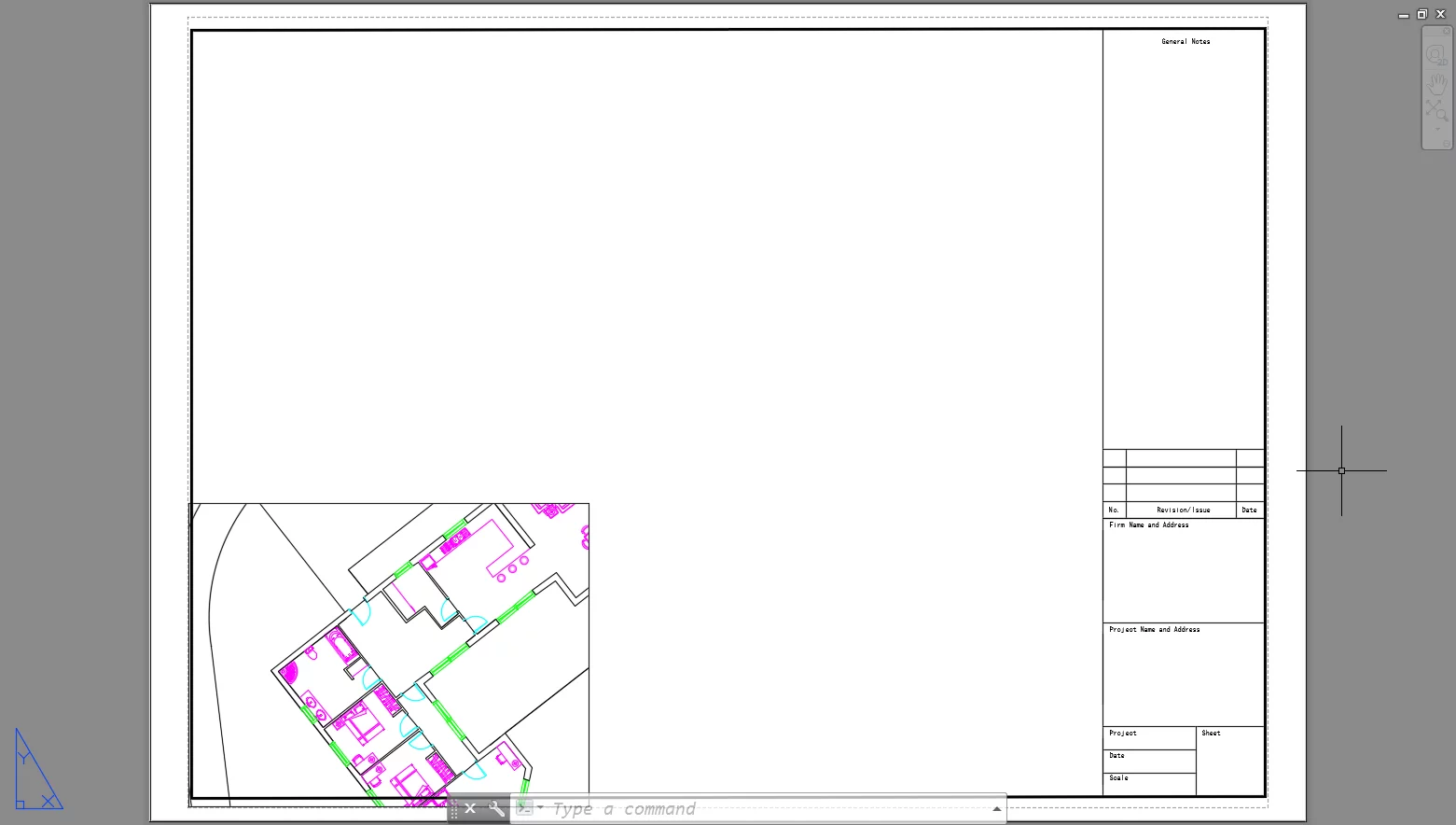
Check that your title block has been inserted correctly. Use the move, scale or stretch command as required until your title block looks just right:
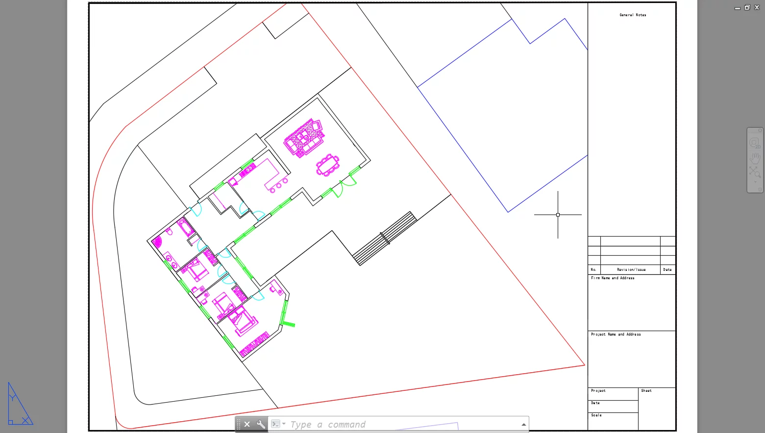
The next thing you are going to want to do is setup some viewports. These allow us to see into model space and place a chunk of it onto our newly created page layout. Edit the scale by double click entering the viewport and set the scale as required via the scale list:
Adjust the size of the viewports by stretching the nodes to the required size. In this case, we will use all of the paper space available within the title block to show the building and site of the Corner Drive project:
Tip 22 – Use Fields to Auto Enter Title Block Information
One of the biggest chores after creating and placing the title block is entering title block information.
Thankfully, and what many users may not know, is that AutoCAD can auto generate much of this information and place it accordingly for us.
Type the command FIELD↵, to explore some of the options available.
Step 19 – Lineweights & Plot Styles
While you may think that once you have created a drawing and placed it nicely in a layout that you are ready to print.
You would be wrong. Instead, you are going to want to start thinking about line weights if you have not already done so.
Lineweights are important in the architecture and engineering world as they can be used to make a drawing legible, and add a necessary hierarchy.
They can, however, be quite a frustrating ordeal if we do not know how to set them for print.
Many users that try to set up lineweights within AutoCAD may be inclined to plumb directly for setting them up within the Properties Palette or Layer Properties Manager.
Though this is not at all recommended. Instead, the most effective way to set up your line weights for print is to edit or create a plot style table.
To create a plot style table navigate to the print dialogue by entering Ctrl + P or by entering the command PRINT↵.
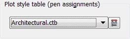
You have no doubt all accessed the print dialogue before, but may not have noticed in the upper right corner is the “Plot Style Table” section.
Click on the drop down menu contained within the Plot Style Table section and click “New”:
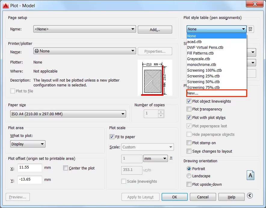
Alternatively, if you want to edit an existing plot style table, select the plot style you want to edit from the drop-down menu and click on the Edit button to the right of the drop down menu.
After you have clicked “New” the Add Colour Dependant Plot Style Wizard will open and present you with three options:
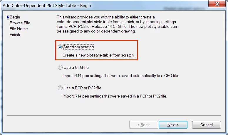
Click the “Start from scratch” option and give your plot style table an appropriate name as prompted on the step that follows.
In this example, we created a plot style from scratch using the file name “Architectural”.
The last step of the wizard will offer you the opportunity to set your newly created plot style table as the default for future drawings or to set it as the plot style for the current drawing:
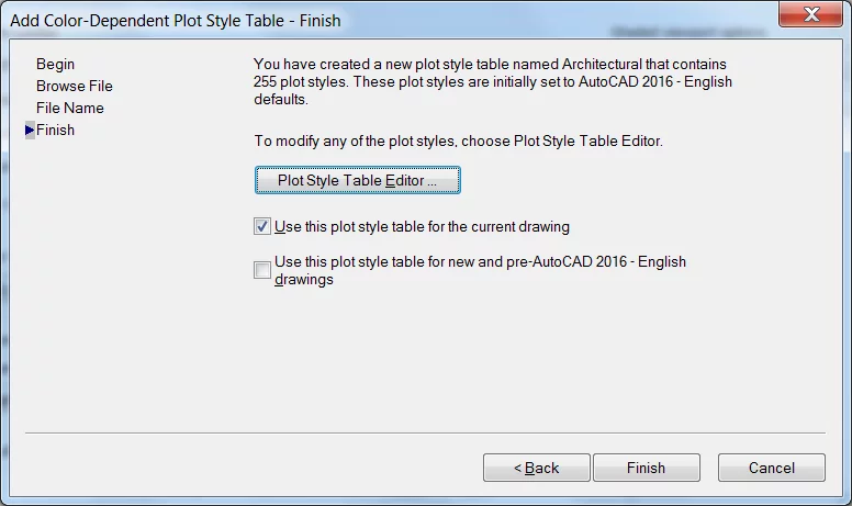
Note: this choice can be changed later so don’t feel the need to study the options available too much.
After clicking finished, you will have in turn created a new plot style table.
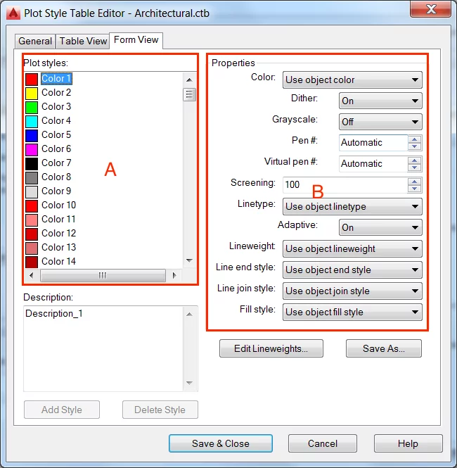
Click on the Edit button to start setting the lineweights and plot style for each colour within your drawing:
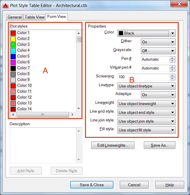
You will notice that listed within the Plot Style Table Editor is all of the 255 standard line colours found within AutoCAD (A).
You can begin changing line weights and other properties by clicking on the colour you wish to edit (B):
In the example project, Corner Drive, you may have noticed in previous sections only a finite number of colours were used when setting up layers, and they ranged primarily from colours 1 to 10.
This was so as to make plot styles easier to set up.
As colour 6 was used for the Furniture layer, we are probably going to want this to be a thin lightweight so as to make the finer details of the furniture objects legible.
This can be done by adjusting the lineweight within the Plot Style Table Editor:
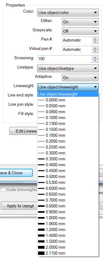
Note: By setting the lineweight within the Plot Style Table Editor you have overridden the object line weight as set up within the Properties Palette and Layer Properties Manager.
Tip 23 – Set Line Colours using Plot Style Tables
There is a whole host of properties that are needed when draughting with AutoCAD, but not ideal when it comes printing.
These can all be overriding within the Plot Style Table Editor. For example, a property you are probably going to want to print differently to how it is displayed within AutoCAD is line colour.
AutoCAD offers the option of a Monochrome Plot Style, within the Plot Style Table section of the Print dialogue.
To change line colour within one of the other standard plot style tables or a custom created plot style table, open the Style Table Editor and using the Shift key select all of the colours contained within the table (A):
Next, change the Colour option within the Properties section of the Plot Style Table Editor to Black (B).
This will change all of the selected plot styles to Black, when you print.
Though it is likely that you may want some colour within your printed drawing. For example, standard practice dictates boundaries lines should be red.
As such consider setting colour 10 to “Red” or “Use object colour”. Remember though to make sure your boundary line layer is actually drawn using colour 10 or whichever colour you choose.
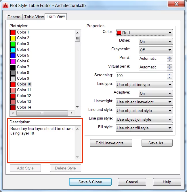
You may want to consider using the Description section of the Plot Style Table Editor, to remind you and others of the logic behind the Plot Style Table.
Tip 24 – Load Plot Style Tables into Other Drawings
After you have been using AutoCAD for some time you probably will have perfected line weights and other plot styles.
At this stage you may want to think about sharing them with others are want to access them quickly when working on other computers.
This becomes a straightforward task, because plot style tables are saved externally as .ctb files.
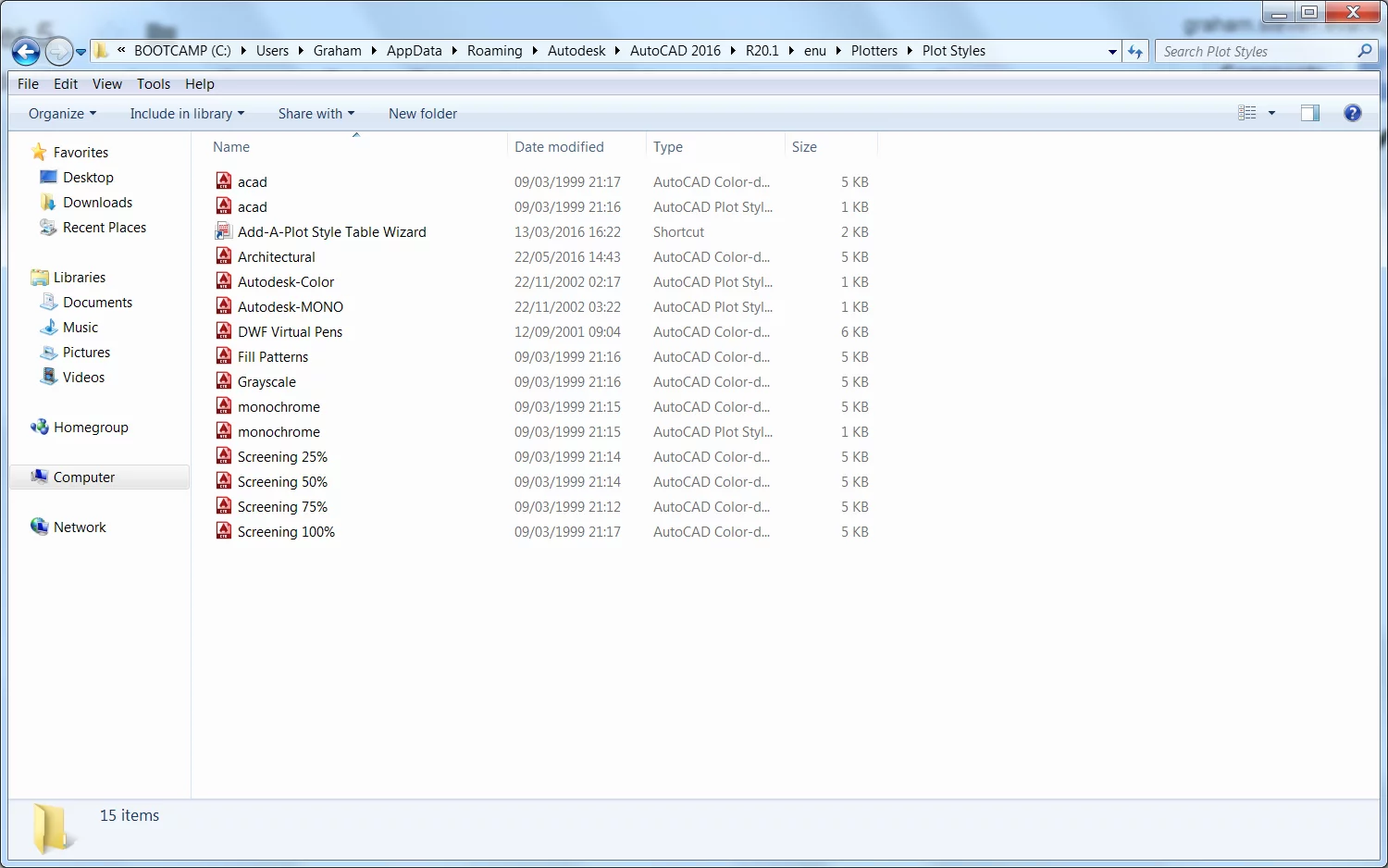
To access the .ctb file simply type the command PLOTTERMANAGER↵.
This will open container folder of the “Plot Styles” folder within your local hard drive. From which you can access custom and default plot style tables:
Copy the .ctb file for later and add it to the Plot Styles folder of other computers you want to access it from.
Looking to get started with some soft skills? Check out our 10 tips for delivering presentations here!
